IQUART Flight Controller Interface
Module Support
To see if your module and firmware style supports this feature, please see our supported features table.
About IFCI and Control Values
Vertiq modules may be controlled through the IQUART Flight Controller Interface (IFCI) when running applicable firmware. The IQUART Flight Controller Interface leverages Vertiq’s IQUART serial protocol in order to send high speed controls to your modules. These controls are packed into a single message allowing one IFCI packet to send controls to multiple modules connected to the same serial line. The basic structure of an IFCI packet is illustrated below:
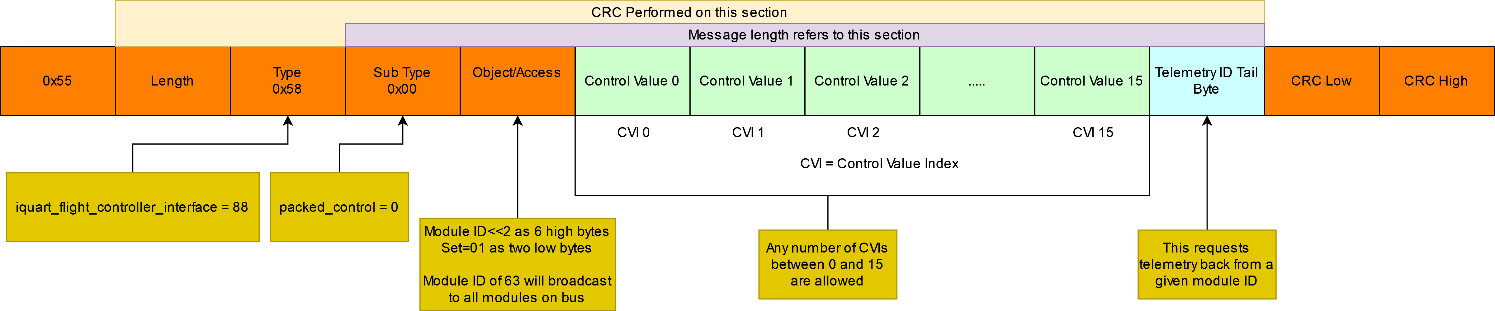
Packed Control Message Description
Please note that an IFCI packet does not necessarily need to populate all 16 control values.
Highlighted in orange are the bytes that are necessary in order to send valid IQUART messages, and are not specific to IFCI control.
Highlighted in green are Control Values. A control value is an unsigned 16 bit value that defines a throttle, an X, a Y command, or a unitless servo command. X and Y commands are only applicable when using Vertiq’s pulsing firmware. Unitless servo commands are available when using servo firmware versioned 0.1.0 or later. More information about controlling with unitless servo commands can be found in our position documentation.
Any type of command can occupy any control value, and the location it occupies in an IFCI packet is called its Control Value Index (CVI). For example, suppose you want to control a generic quadcopter. You may place the throttle commands for motor 1 in CVI 0, commands for motor 2 in CVI 1, and so on. Since the control values’ order is fully configurable, however, it would be equally valid to place motor 4’s throttle command in CVI 0.
Having the ability to place any control value in any index also means that you must configure your Vertiq module to know which control value indices to read for its specific commands. For example, suppose your flight controller is configured to transmit 10 control values. The throttle command for the module being configured is the 5th command (CVI 4) in the IFCI packet. In order to have the module listen to that command, you simply set its Throttle CVI to 4. The same principle applies to X and Y commands as well.
Note
If the CVI for any of the control values needed by a module is set to 255, then the module will not attempt to extract the control value from any index in the IFCI packet.
All module Control Value Index values can be found in the Type ID 88 | IQUART Flight Controller Interface. You can also find the CVIs in the Control Center’s general tab:

Mapping Received Control Values to Motor Control Outputs
As mentioned above, all IFCI control values are represented by unsigned 16 bit numbers representing an integer range from [0, 65535]. How these values are mapped into commands applied by your module is dependent on the control value type (throttle, X, or Y) as well as other module configurations.
Mapping Throttle Control Values to Applied Spin Throttle
Before continuing, please familiarize yourself with the basics of your module’s Modes, Maximums, and Direction found here.
Throttle control values are subject to the same behaviors governing both timer based and general IQUART throttle inputs. In fact, throttle control values are processed by the same pipeline as the IQUART raw value.
In order to calculate the raw value that your module will apply, simply divide the received throttle control value by 65535. That value is then mapped to applied throttle based on your modes and directions.
Suppose your module is configured to spin 2D counterclockwise with 2D FC Mode, and is set to velocity mode with a maximum of 1000 rad/s. Now, your module receives an IFCI packet that has data in your module’s Throttle Control Value Index with the value 26000. The equivalent IQUART raw command is \(\frac{26000}{65535} = 0.397\). In this case, the applied throttle percentage is calculated simply by \(0.397 * 100 = 39.7\%\). Since we are in velocity mode with a maximum velocity of 1000 rad/s, your module is set to spin at \(0.397 * 1000 = 397 rad/s\) in the counterclockwise direction.
Now, you change your module’s sign to 3D clockwise with the same flight controller direction. We once again receive a throttle control value of 26000. Our raw command remains \(\frac{26000}{65535} = 0.397\). Since our module’s sign has changed, and it can now spin both clockwise and counterclockwise, the applied velocity command is calculated differently. Using FC Mode = 2D, Motor Direction = 3D, you can find that the applied throttle percentage is now \(((0.397 * 2) - 1) * 100\% = -20.6\%\) . In this case, the negative sign indicates that the module will spin \((0.206 * 1000) = 206 rad/s\) in the counterclockwise direction.
Mapping X and Y Control Values to Applied Pulsing Values
Like throttle, in order to calculate the raw value that your module will apply to either the X or Y pulsing command, simply divide the received control value by 65535. The raw value is then mapped to the range [-1, 1].
Suppose your module receives an X control value of 42000. The equivalent raw value is \(\frac{42000}{65535} = 0.641\). In order to map that value onto [-1, 1], simply multiply it by two and subtract one. In this case \((0.641 * 2) - 1 = +0.284\).
Your module also receives a Y control value of 1000. The raw value is \(\frac{1000}{65535} = 0.015\), and the Y control percentage is \((0.015*2) - 1 = -0.97\).
In the Pulsing Rectangular Input Parser, the setting pulsing_voltage_mode controls whether this value is considered a percentage of supply voltage or a percentage of the
value defined by pulsing_voltage_limit. When set to supply voltage mode -1.0 maps to a pulsing voltage on that axis of negative battery voltage and 1.0 maps to positive
battery voltage. When set to voltage limit mode you must also set the pulsing_voltage_limit parameter. This will set the maximum and minimum pulsing voltage.
In this mode -1.0 will map to -pulsing_voltage_limit and 1.0 will map to pulsing_voltage_limit. Between these values, the raw value is linearly mapped to the voltages in
between. For example if the battery voltage is 12V and pulsing_voltage_mode is set to 0 then -1.0 would map to -12V of pulsing, 0.0 would map to 0V, and 1.0 would map to 12V.
With the same battery voltage, but pulsing_voltage_mode set to 1, and pulsing_voltage_limit set to 4.0, -1.0 would map to -4V of pulsing, 0.0 would map to 0V and 1.0 would map
to 4V of pulsing.
Mapping Unitless Servo Control Values to Applied Actuation
Like other control values, the raw value applied to unitless controls is calculated by taking the received control value and dividing 65535. For example, a control value of 30000 results in a raw command of \(\frac{30000}{65535} = 0.46\).
This value is passed to the Type ID 78 | Servo Input Parser, and is treated identically as raw values sent over timer based protocols.
Suppose your unit_min is set to -20, your unit_max to 50, and your mode to 3 (angular displacement). Taking the same control value of 30000, we can find the target actuation
point by taking \(\text{unit min} + (\text{raw value} * (\text{unit max} - \text{unit min}))\) or \(-20 + (0.46 * (50 - (-20))) = 12.04\).
When in angular displacement mode, this means that your module will rotate to an angular displacement of \(12.04 rad\).
Now, suppose you change your mode to 2 (velocity), and continue sending the same command. The commanded value remains \(12.04\), but the actuation is now a target
velocity of \(12.04 \frac{rad}{s}\).
IFCI Telemetry
There are two methods to request module telemetry with the IQUART Flight Controller Interface. First, as mentioned above, simply fill the Telemetry ID Tail Byte of a IFCI packet with the module ID whose telemetry you want. Second, you can perform a Get request on the module’s IQUART Flight Controller’s telemetry entry. In either case, the data returned by the telemetry endpoint contains 16 bytes. A struct called IFCITelemetryData is required to store this data. Here is a description of the IFCITelemetryData struct:
struct IFCITelemetryData
{
    int16_t mcu_temp;       // Temperature of the microcontroller in centi °C
    int16_t coil_temp;      // Temperature of the coils in centi °C
    int16_t voltage;        // Supply voltage in centi-volts
    int16_t current;        // Supply current in centi-amps
    int16_t consumption;    // Consumtion in mAh
    int16_t speed;          // Velocity of the motor in rad/s
    uint32_t uptime;        // Uptime in seconds
};
Note
Your module can be configured to report speed rather than velocity in its IFCI Telemetry response. To do so, simply set Report Telemetry as Speed in IQ Control Center’s
advanced tab to Enabled.

Connecting Modules for IFCI
While IFCI can work to control a single module connected to a single UART port on your flight controller, you can also connect multiple modules to a single UART port for control as a bus. An example of the connection is shown below.
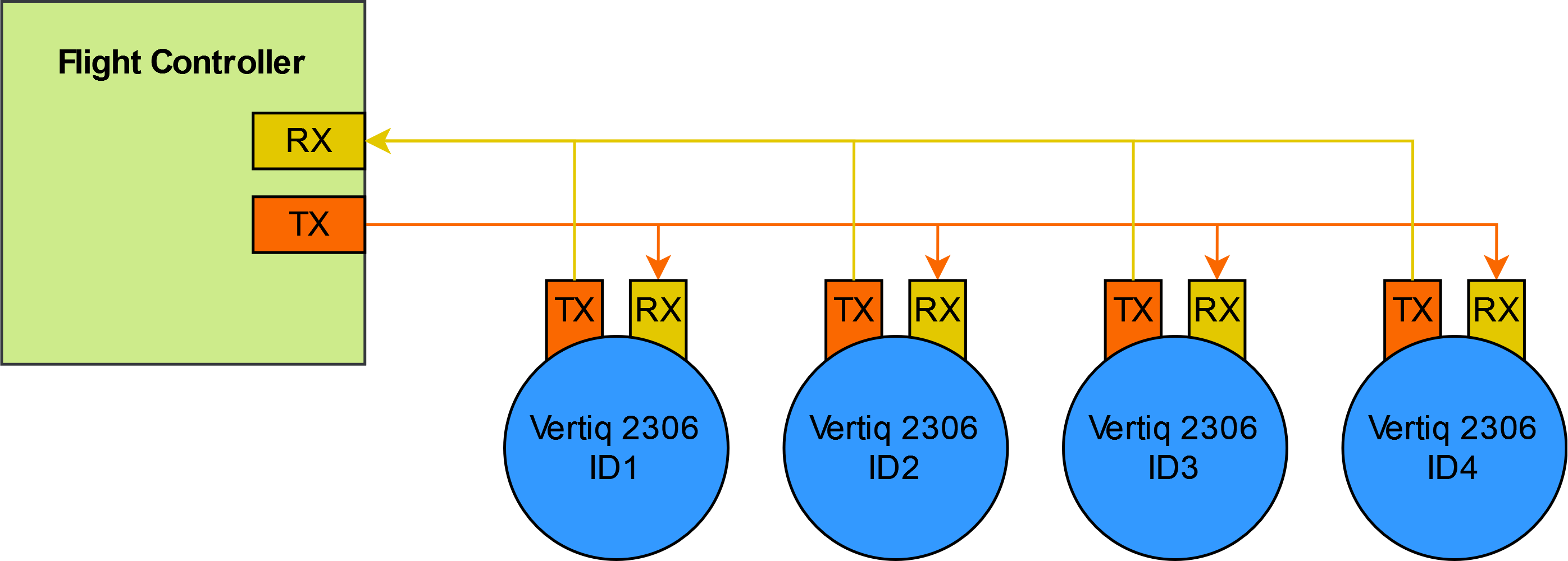
Bussed Serial Connection
This will allow you to control the modules individually using control values and CVIs without changing the module IDs, but if telemetry is required you will need to set each module’s module ID to a different value. This is done in the system control client with the ‘module_id’ parameter. Each module on the bus should have a unique module ID.
To request telemetry via the packed control message, the Telemetry ID Tail Byte (TITB) must be set to the module ID of the module whose telemetry is desired. When this is set, the corresponding module will immediately reply with a telemetry packet. To get every modules’s telemetry, the flight controller must ask each module for telemetry individually. If you are sending control messages on an aircraft with 4 motors at 400Hz, then you can receive telemetry from an individual module at a maximum of 100Hz. The telemetry data is packed in a standard IQUART message and the data structure is described in IFCITelemetryData struct.
Some examples of different aircraft configuration’s data packets are shown below:

Example quadcopter data packet
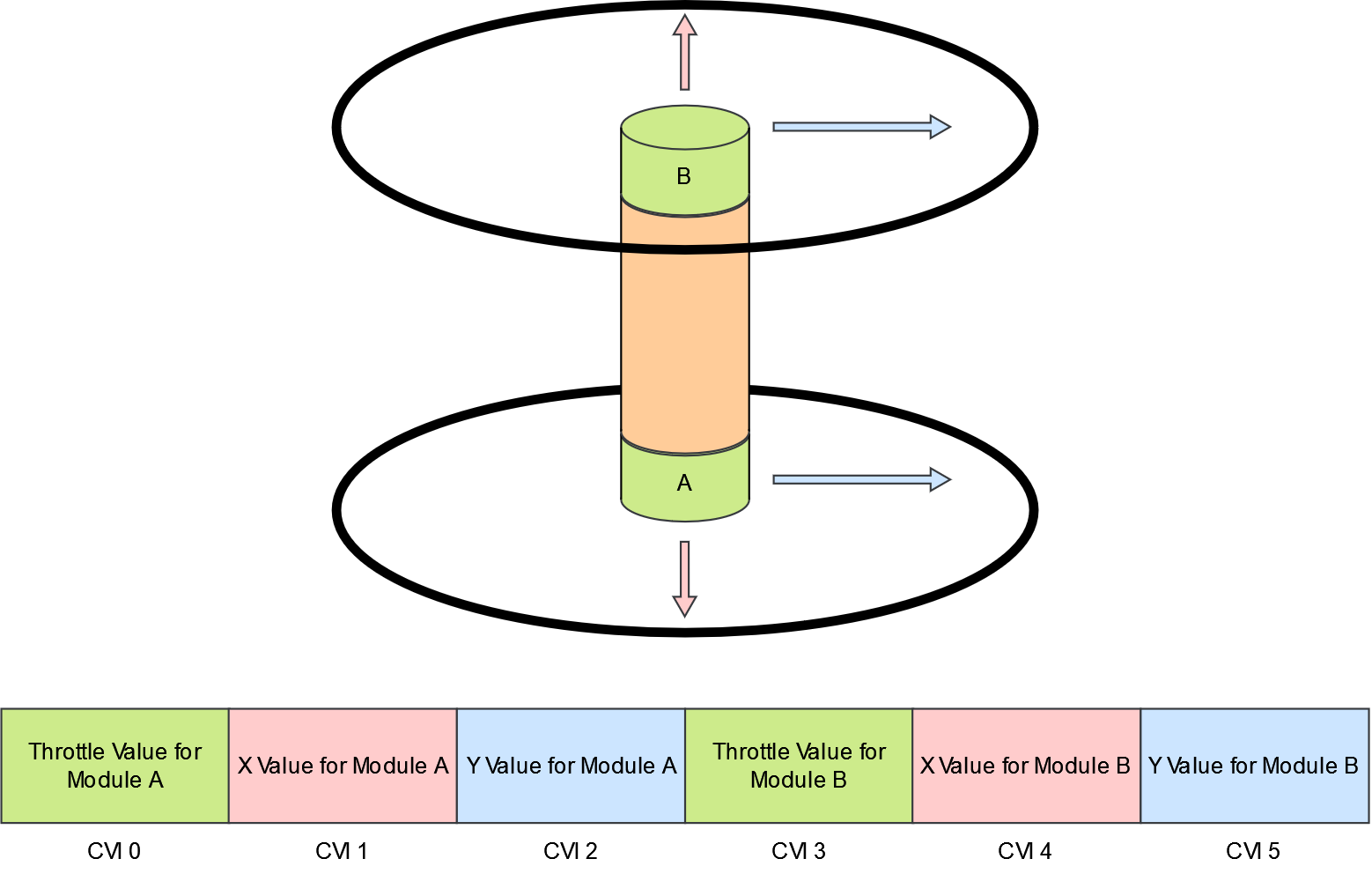
Example coaxcopter data packet
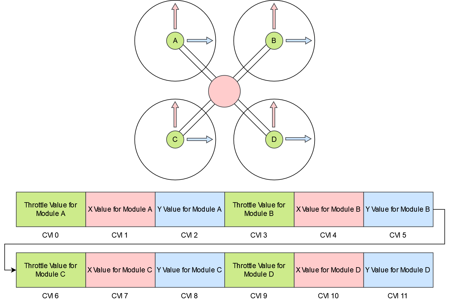
Example 6-DOF quadcopter data packet
The control values’ order does not matter so long as they match between the flight controller and the module’s settings. Additionally, two modules may read the same CVI if they are to respond identically to, or in reverse from one another.