Communication Errors and Motor Noise
Where Does Motor Noise Come From?
Electric motors produce torque through interactions between the motor’s permanent magnetic field and the electric current flowing through the motor’s wire windings. The electric current in the motor’s windings produces a variable magnetic field which can be controlled to exert a force on the motor’s permanent magnets/magnetic field. Current is directed through the motor’s windings by applying a voltage across the windings. The direction the current flows through the windings can be switched by changing the voltage polarity across the windings. In a three phase brushless DC motor like those produced by Vertiq, the three windings are connected between each of the three phases as seen below in figure 1. The process of directing the current through the coils of a three-phase motor is known as commutation.
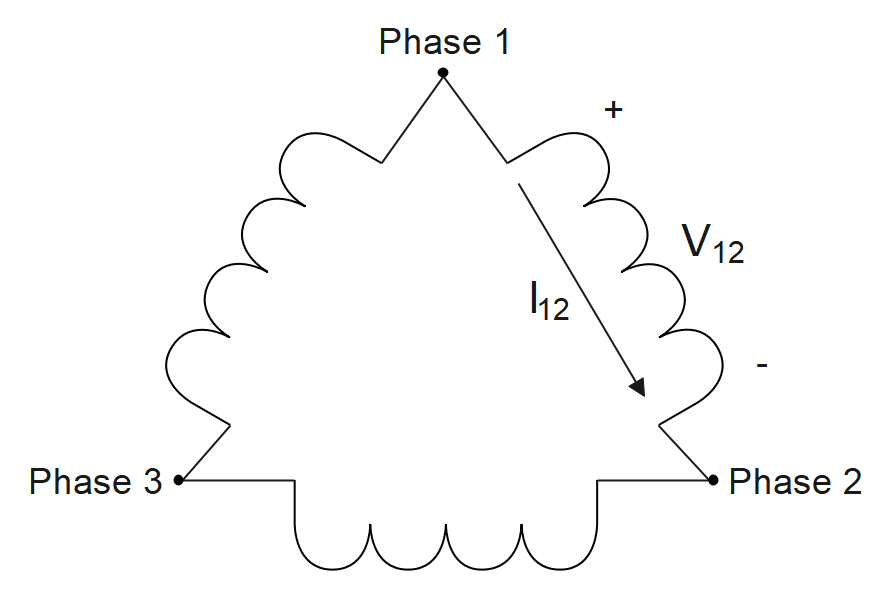
Figure 1: Simplified Phase Wiring Diagram
However, motors are neither perfect nor closed systems. The same switching voltages that occur during commutation to spin the motor may also cause electromagnetic interference (EMI) in nearby electronic systems, including those used to drive and communicate with the motor. EMI originating from an electric motor is what we call motor noise. EMI can be radiated, coupled, or conducted and can occur at different frequencies and their harmonics. Therefore, it is important to understand the sources and impacts of EMI when designing mitigation techniques.
This tutorial will address the mitigation of motor noise that couples to a motor’s body through stray capacitances inside the motor. Stray capacitance (also known as parasitic capacitance) will exist between two conductors that are physically close to each other and carry different potential voltages. The electric field between the two conductors will store a small charge which creates an effective capacitance. Stray capacitances are typically in the picofarad range. Unfortunately, a few picofarads is enough to couple significant motor noise to the motor’s body. Noise coupled to a motor’s body can then be conducted to conduits carrying communications cables such as a vehicle frame or drone arm. Motor noise may also be radiated from the motor and its coils, but the impacts of radiated noise on unmanned vehicle systems tend to be less significant and the same techniques can be used to mitigate them.
Why Are Internal ESCs More Susceptible To Noise?
Drones that utilize electric motors with integrated ESCs tend to have longer communication wires than vehicles that use external ESCs. This is because external ESCs are typically installed close to a drone’s power distribution unit to keep DC wire length short. Therefore, the communications buses only need to be routed to the ESCs’ locations and the three phase motor cabling will extend along the arm to reach the motor itself. A simplified diagram of a drone wired with external ESCs can be seen below in figure 2.
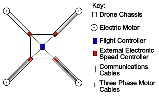
Figure 2: Simplified Drone Cabling Diagram With External ESCs
Conversely, a drone utilizing motors with internal ESCs will have communications cables extending the entire length of the drone arm to reach the motor as seen below in figure 3. Generally speaking, a communication network’s susceptibility to EMI will increase the longer its wire lengths get. Therefore, it is especially important to reduce EMI and build robust communication buses on a vehicle utilizing motors with internal ESCs.
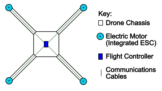
Figure 3: Simplified Drone Cabling Diagram With Internal ESCs
Identifying Noise On Communication Lines
When an electric motor is mounted to a conductive frame with metal or conductive screws, the motor body and vehicle frame will be electrically connected. In this scenario, it is likely that any motor noise that couples to the motor’s aluminum body via parasitic capacitances will conduct onto the vehicle’s frame. Communication buses that run through or parallel to a noisy vehicle frame will be susceptible to the interference and may experience dropped packets or communication failures. The oscilloscope screen capture below in figure 4 displays how motor noise that has been conducted onto a carbon fiber tube can interfere with signal buses that are routed through it. A simulated drone setup was used to capture the scope images in this document and can be seen below in figure 5. In this example the carbon fiber tubes used to simulate drone arms are one meter in length and electrically connected.
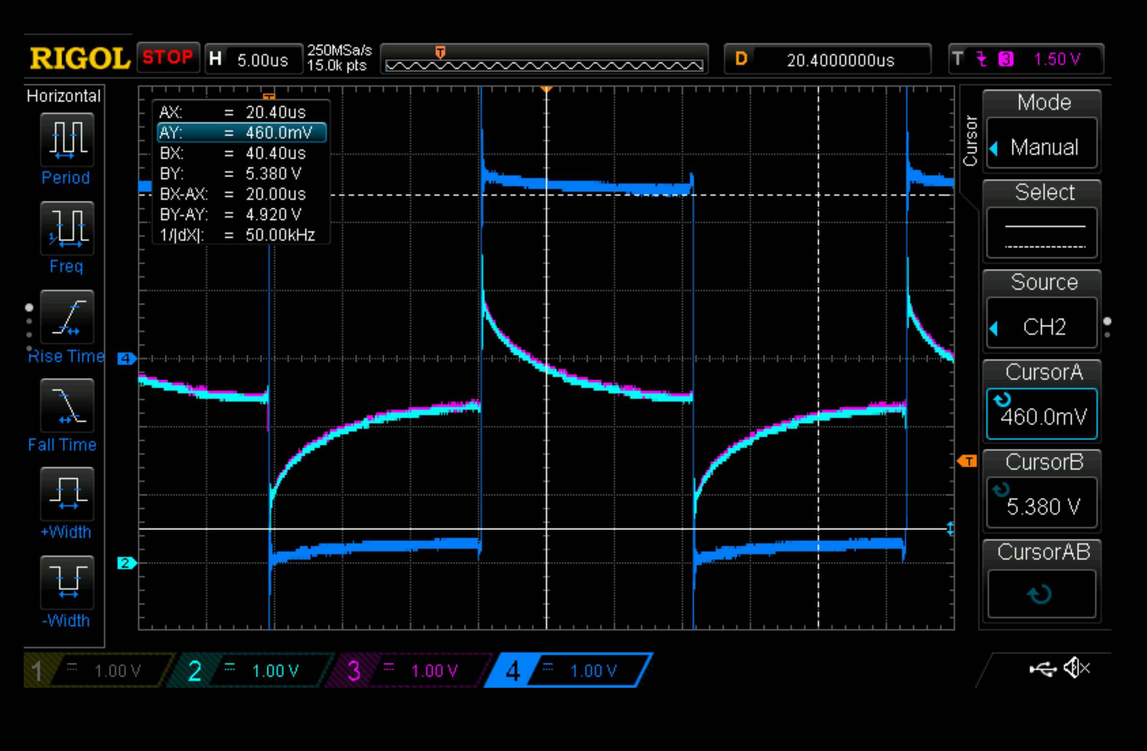
Figure 4: Coupled Motor Noise
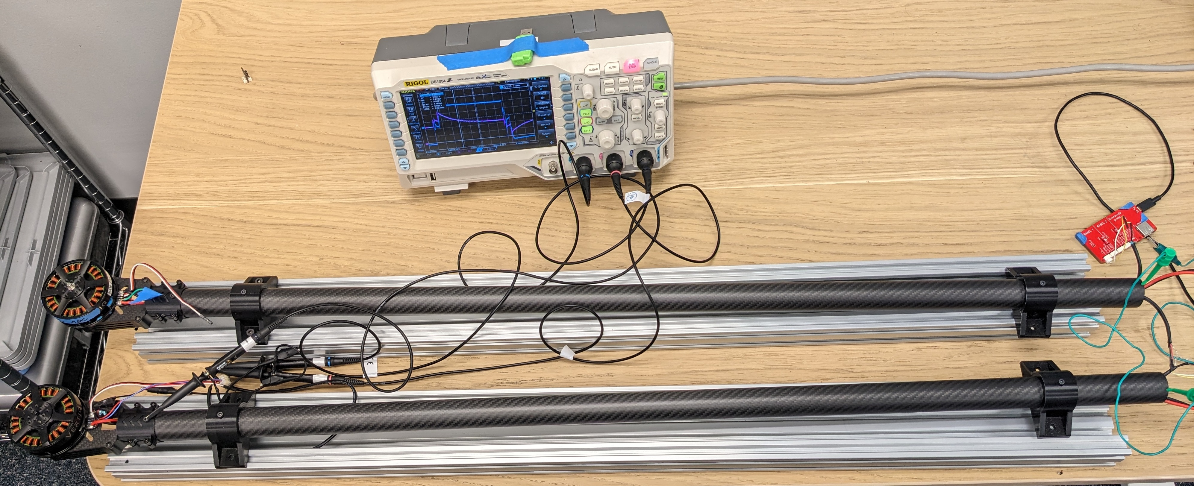
Figure 5: Simulated Drone Communication Noise Setup
Channels 2 and 3 (light blue and pink) in figure 4 display CAN bus high and low signals at a recessive voltage state (i.e. no signal is actively being transmitted). Channel 4 (dark blue) is measuring motor noise that has been conducted on to the carbon fiber tube “drone arms”. One can clearly observe the motor noise is interfering with the communication bus during each of the electrical transitions. One may also note how the motor noise on the frame has a DC (the “on” and “off” voltage at +/-2.5 V) and an AC (the transition between the two DC states) component, but only the AC component is coupling via the stray capacitance.
How To Minimize Noise On Communication Lines
Motor noise can be insulated from a vehicle’s frame by mounting the motor using nylon or nonconductive spacers and/or screws.
However, designers of heavy duty vehicles often want to avoid using nonconductive plastic fasteners as they are mechanically weaker than metal or carbon fiber and act as thermal insulators. Fortunately, motor noise coupled to a motor’s body can also be eliminated or greatly diminished by connecting the motor body or vehicle frame to power ground. Whether or not to ground a motor body and/or vehicle frame is a decision with many application specific considerations. Frame grounding will be discussed in greater detail in the next section.
Frame Grounding
Grounding Considerations
Electronic enclosures and cases are commonly grounded at a single point close to the power supply ground to reduce EMI and improve user safety. This is an easily applicable standard for a single motor with an integrated ESC where a mounting screw can be used to ground the motor chassis. Grounding through a mounting screw in the motor itself is particularly effective in reducing motor noise as it provides a very low impedance path for coupled noise to drain back to ground.
However, a vehicle with multiple motors will have multiple grounding points on its frame if the motors are not mounted using electrically isolating features. One must also consider whether or not the other electronic devices mounted to the vehicle’s frame have their mounting positions tied to ground or potentially even a positive voltage. Unfortunately, there is no one standard for electronic enclosure or PCB mounting hole grounding/isolation. Therefore, one should perform a continuity check between the power connectors and the enclosure/mounting position(s) of each device being mounted to a vehicle frame so that all power paths can be considered and short circuits can be avoided.
Grounding Schemes
Power Supply Grounding
The simplest grounding scheme is to connect the drone frame to ground at a single point near the power source ground, which will usually be near the center of a drone. A simplified diagram of a drone using a power supply grounding scheme can be seen below in figure 6.
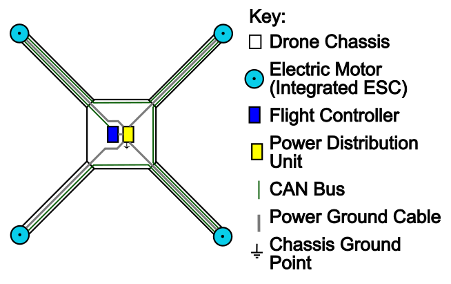
Figure 6: Power Supply Grounding
A scope image of a CAN bus utilizing a single point of grounding near the power distribution unit can be seen below in figure 7. Channels two and three (light blue and pink) display CAN bus high and low signals, but this time a data transmission is occurring on the bus. Here we can see how using the power supply grounding scheme on the simulated drone frame has essentially removed the DC noise on channel 4 (dark blue). However, the AC spikes can still be observed due to the impedance of the carbon fiber tube that separates the motor chassis and the frame’s centralized grounding point. The noise on channel 4 can also be seen to interfere with the CAN bus signals.
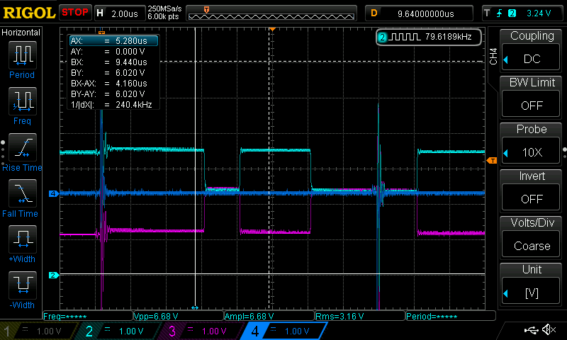
Figure 7: Single Point Grounding
The AC noise present on the signal bus can be mitigated by using shielded twisted pair cable. The cable shields should have their drains connected to ground at the same location as the frame. Differential buses like CAN are designed to be resistant to the common mode noise illustrated in figure 7 and may be operational in this grounding scheme. However, if communication failures persist or design requirements can not tolerate the interference, one may need to consider locally grounding each motor body.
Motor Body Grounding
Motor noise that has coupled to the motor body can be effectively eliminated by grounding the motor body to power ground. A simplified diagram of a drone using a motor body grounding scheme can be seen below in figure 8. Please note that the simplified drone in figure 8 also has a grounding point near the power distribution unit. This ground point is technically optional, but recommended to help keep the drone frame ground at a common voltage. The importance of keeping the frame at a common ground voltage will be elaborated on later in this section.
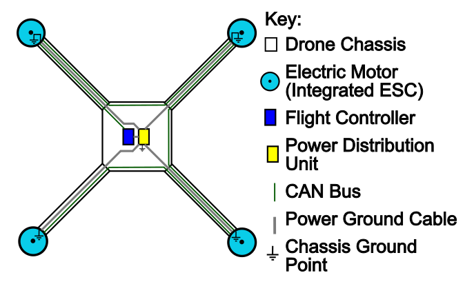
Figure 8: Motor Body Grounding
An oscilloscope screen capture containing the simulated drone communication test results can be seen below in figure 9. The motor bodies in this test are internally connected to ground via a PCB mounting screw. Once again, Channels 2 and 3 (light blue and pink) display a CAN bus with signals actively being transmitted and Channel 4 (dark blue) is displaying the voltage on the carbon fiber frame. Here we can see a significant absence of motor noise on all channels. While the results of eliminating motor noise by grounding the motor bodies are very encouraging, having multiple ground locations on a single vehicle frame introduces further design considerations.
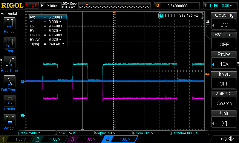
Figure 9: Motor Body Grounding
Having multiple grounding points on a vehicle frame may cause the frame itself to conduct currents, which are sometimes referred to as parasitic currents or ground loops. Parasitic currents will flow when there is a voltage difference between two points that are nominally ground referenced and may exacerbate communication issues. Ground loops are a problem typically found in applications with large cable lengths where small currents can produce large voltage offsets like the AC mains in buildings. Ground loops may not be an observable problem on relatively smaller scales such as unmanned vehicle frames. However, if communication errors are occurring on a vehicle with multiple frame grounding locations that do not occur when the frame is isolated or only has one connection to ground, ground loops may be the cause. Ground loops can be eliminated by using isolated mounting methods such as plastic or nylon spacers and screws.
When designing a vehicle where it is necessary to ground the vehicle frame at multiple points, please consider the following to help keep the vehicle frame at a common potential:
Make a frame ground connection point as close as possible to the power supply/battery ground.
Ground each motor body close to the power ground input using the most direct method possible, such as a grounding screw.
Make a frame ground connection point close to the power ground input of each electronic device on a communication bus.
Use the shortest possible cable length when connecting each electronic device’s power ground to the power supply/battery ground. This should result in the power network having a star topology with the power supply/battery connection in the center.
Use a sufficiently thick wire gauge for the current application when making ground connections.
In general, frame ground paths between an electronic device and the power supply/battery should have a single parallel power ground path through the power ground cable.
Avoiding Frame Ground Faults
When designing a vehicle with a grounded frame or chassis, it is important to consider and protect against potential faults that would not occur if the frame was floating. For example, if a cable carrying a positive voltage, such as the battery voltage, is damaged and makes contact with a grounded frame it will likely cause a vehicle wide power failure and potentially damage other on board electronics.
Similarly, if a power ground cable becomes damaged or disconnected on a vehicle that is grounded at multiple points, the vehicle frame may act as a power ground bus and conduct the full ground current. Using a vehicle frame as the power bus may be common in the automotive industry, but is typically a bad idea for drones depending on what material the frame is constructed from. For example, the sturdy and lightweight material carbon fiber has a relatively high resistivity compared to aluminum or copper. A material with a higher resistivity will produce more waste heat at the same current load than a material with a lower resistivity. Therefore, conducting power ground through standard carbon fiber at high operating currents may create a fire hazard.
To prevent ground faults associated with cabling, cable harnesses should be designed with mechanical features required for use in high vibration environments. Examples of vibration resistant features include, but are not limited to the following:
Cable connectors with locking or clasping features.
Cable routing with strain relief.
Rounding or filleting sharp corners, especially near cable routings.
Additionally, consider making redundant ground connections through a fuse or polymeric positive temperature coefficient device (PTC) to prevent high current flows through a carbon fiber frame.
Grounding Your Vertiq Module’s Frame
Vertiq’s Pro Kit modules, as well as many Vertiq G2 modules are shipped with a user accessible, nonpopulated component footprint. This footprint provides a convenient method for connecting the module’s frame to the V- electrical ground through a mounting screw. Illustrations of the 40, 60, and 81 sized modules and their connector boards are provided below. The nonpopulated footprint’s pads and the mounting screws are labeled:
Solder pad connected to V-/ground
Solder pad connected to grounding screw
Grounding screw
Mounting screw
Note
Component designator labels (F1, R1, etc) may not appear on the connector board’s silkscreen.

Figure 10: 40 sized module with CN2.1.2 Connector

Figure 11: 40 sized module with CN3.1.0 Connector

Figure 12: 60 sized module with CN5.1.0 Connector

Figure 13: 60 sized module with CN6.2.0 Connector

Figure 14: 81 sized module with CN8.1.0 Connector

Figure 15: 81 sized module with CN10.2.0 Connector
To ground the module’s frame, a PTC or 0 ohm resistor should be soldered to the footprint pads labeled 1 and 2 in the relevant image above. Use of a fuse is recommended as a fuse will prevent excessive current draw in case of a fault. A 0 ohm resistor will not open circuit during a fault, which could cause serious damage to the airframe and module. One pad of the component footprint is connected directly to the V- ground input while the other pad is tied to an exposed grounding pad underneath the nearby mounting screw (3). The mounting screw will provide an electrical path from the grounding pad to the module’s frame. The standard footprint sizes of the component pads and recommended part numbers can be found below:
- 40-XX
- CN2.1.2: US 0805 (M 2012)
PTC PN: 0805L005/30YR
0 ohm Resistor PN: ERJ-6GEY0R00V
- CN3.1.0: US 0805 (M 2012)
PTC PN: 0805L005/30YR
0 ohm Resistor PN: ERJ-6GEY0R00V
- 60-XX
- CN5.1.0: US 0805 (M 2012)
PTC PN: 0805L002YR
0 ohm Resistor PN: ERJ-6GEY0R00V
- CN6.2.0: US 0603 (M 1608)
PTC PN: 0ZCM0002FF2G
RMCF0603ZT0R00
- 81-XX
- CN8.1.0: US1206 (M 3216)
PTC PN: 1206L005/60WR
0 Ohm Resistor: RMCF1206ZT0R00
- CN10.2.0: US1206 (M 3216)
PTC PN: 1206L005/60WR
0 Ohm Resistor: RMCF1206ZT0R00
Continuity between the solder pad and the module’s frame can be confirmed using a multimeter between the pad labelled 1 (V-/ground net of the solder pad) and the screwhead labelled 4 (mounting screw opposite of the grounding screw). If continuity cannot be established when both screws and the grounding component are in place, then tighten the screws a bit and try again, repeating as necessary. If using a PTC, please consider the nominal resistance of the device when performing the continuity test. Testing continuity should be done to confirm that the mounting screw is touching and electrically connected to the grounding pad on the PCB. Tightening the screws will also help the mounting screw pierce the black anodization applied to the module frame inside the screw hole, which can resist the flow of grounding current.