Stow Position
The stow position feature allows a Vertiq module to return to a configurable position on a transition from armed to disarmed, on timeouts, or when given an explicit command to stow. This can be useful for holding propellers in an aerodynamic position, or preparing vehicles for storage. Users can control what this position is, when the module should attempt to move into the stow position, how aggressively it moves to the stow position, and the module’s behavior once it reaches the stow position. Note that incoming commands can cause interruptions to the stow process, as detailed in Interrupting Stow.
Module Support
To see if your module and firmware style supports this feature, please see our supported features table.
Stow Process Overview
When a module moves to its stow position, regardles of the reason for the stow, it follows a series of steps to stow properly. First, it begins either accelerating or decelerating in order to reach its stow position with its user-configured stow acceleration. So if the module was still before, it will begin moving, but if it was spinning rapdily, it will keep spinning and gradually slow down. Once the module has come to a stop at the stow position, it will then perform its ending hold behavior, which has multiple options discussed below.
The diagram below summarizes the stow position feature’s state transitions. Note that the stow process may be interrupted at any time, and that certain state transitions are configuration dependent.
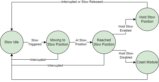
Summary of Process for Moving to Stow Position
Summary of Configuration Parameters
A summary of the different parameters dictating how the stow position feature operates are given below. Note that for all angles, counter-clockwise is considered positive, and clockwise is considered negative. Other sections of this documentation provide greater detail on the usage of some of these parameters.
Stow Angle Parameters
The following parameters pertain to configuring the zero angle for stow and the angle that the module will move to as its stow position:
Stow Zero Angle: This determines what angular position the module will consider as its “zero” position. The target angle is in reference to this angle. Refer to the Configuring the Zero Angle section for more details on how to configure the zero angle.
Stow Target Angle: This determines the angular position of the stow position, with reference to the zero angle. When the module stows, it attempts to move to this target angle. For example, if the target angle is 1 radian, the stow position will be 1 radian counter-clockwise from the zero angle. Refer to the Stow Position Calculation section for more details on how this is used.
Sample Zero Angle: Allows the user to easily set the module’s current position as the zero angle of the module. Refer to the Configuring the Zero Angle section for more details on how to configure the zero angle.
These parameters can be configured under the General tab in the IQ Control Center, as shown below.
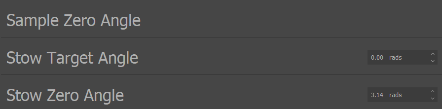
Stow Angle Parameters in IQ Control Center
The Stow Zero Angle can be sampled and the Stow Target Angle configured using DroneCAN as well, see the DroneCAN configuration parameters documentation for details.
Hold Stow
Note
In speed firmware versions prior to v0.2.0, the only options for Hold Stow are Coast When Stowed and Hold Stow. The Brake When Stowed and Low Power Hold options were introduced in v0.2.0.
The Hold Stow parameter determines how the module will behave once it has reached its stow position. The module can coast, brake, or hold its position in two different ways. Refer to the Holding Position section for more information on these different options.
This parameter can be configured under the General tab of the IQ Control Center, as shown below.

Hold Stow Parameter in IQ Control Center
Hold Stow can be configured using DroneCAN as well, see the DroneCAN configuration parameters documentation for details.
Stow Movement Parameters
The following parameters pertain to how the module will move as it transitions to its stow position:
Stow Target Acceleration: Sets the maximum acceleration allowed when moving to the stow position. Can be used to make the transition from spinning to the stow position more gradual.
Stow Kp: The proportional gain to use in the closed loop position controller moving the module to the stow position. A higher gain can lead to a more accurate position, but can also cause oscillation.
Stow Ki: The integral gain to use in the closed loop position controller moving the module to the stow position.
Stow Kd: The differential gain to use in the closed loop position controller moving the module to the stow position.
Stow Target Acceleration can be found under the Advanced tab of the IQ Control Center, as shown below.

Stow Target Acceleration Parameter in the IQ Control Center
Stow Target Acceleration can be configured using DroneCAN as well, see the DroneCAN configuration parameters documentation for details.
Stow Kp, Stow Ki, and Stow Kd can all be found under the Tuning tab of the IQ Control Center, as shown below.
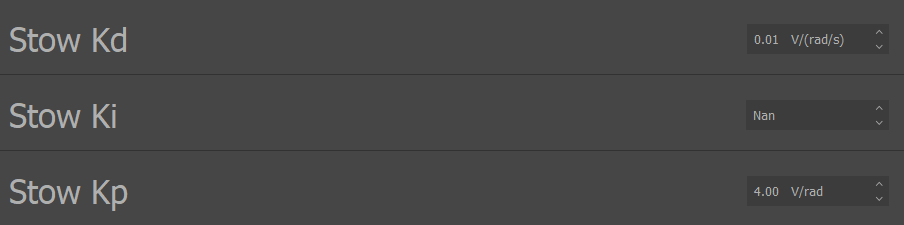
Stow PID Parameters in the IQ Control Center
Stow Position Calculation
The final stow position is calculated based on the zero angle and the target angle. The zero angle determines what angular position is considered to be zero radians. The choice of this position is arbitrary, any angle can be the zero position, it is only important to be consistent so that every module is using the same reference point.
The target angle determines what angular position is considered the stow position. The target angle is always in reference to the zero angle, e.g. a target angle of 1.57 radians means the stow position will be 1.57 radians counterclockwise from the zero angle. By keeping the zero angle consistent and modifying the target angle between -π and π, you can set any possible stow position. The equation below summarizes this relationship between target angle, zero angle, and the final stow position.

Stow Position Angle Calculation
Configuring the Zero Angle
It is possible for users to configure the zero angle of a Vertiq module to any position. There are two approaches to changing the zero angle:
Modify the zero angle directly, setting it to any desired number of radians.
Move the module to the desired position and use the zero angle sampling function to automatically set this new position as the zero angle.
Both of these methods are supported by the IQ Control Center. For the first method, simply change the Stow Zero Angle parameter. It can be increased or decreased by the necessary amount to achieve the desired zero angle.
The second method makes it possible to simply move the module to the position you want, and then sample that as your new zero angle. The steps for this are described below:
Move your module into the desired zero angle. Having a propeller attached to the module may make it easier to determine if you are in the desired orientation.
Connect to the module with the IQ Control Center, and open the General tab.
Click the set arrow on the Sample Zero Angle entry in the IQ Control Center. This will automatically set the current angle as the zero angle.
To test if the zero angle is set correctly, use the Trigger Stow entry in the Control Center. This commands the module to the stow position. Try moving the module to a different position, and then triggering the stow to confirm the module is moving to the expected position.
Triggering Stow
There are multiple possible ways to trigger the module to move into the stow position. Each of these methods is covered in the section below.
All of these methods will cause the module to attempt to move into the stow position, following the procedure outlined in the Stow Process Overview section.
Manual Stow
Users can manually trigger the module to move to the stow position by sending commands over IQUART or DroneCAN. The sections below cover these commands in greater detail.
IQUART
The Trigger Stow parameter can be used to manually request that the module move to the stow position in the Testing tab of the IQ Control Center, as shown below. When this parameter is set, the module will immediately begin the process of moving to its stow position.

Trigger Stow Parameter in the IQ Control Center
DroneCAN
The “motor_stowed” configuration parameter can be used to command the module to stow and release the module if it is holding a stow. This parameter both reports on whether the module is holding a stow and can be used to command stows.
If this parameter is 0 when queried with a Get, that indicates that the module is not holding its stow position. If it is set to 1, that indicates that the module is holding in the stow position.
Setting this parameter to 1 will command the module to move to the stow position. If this parameter is already set to 1, meaning that the module is holding its position, setting it to 0 will command the module to release the hold and coast itself.
The “motor_stowed” parameter can be seen in the DroneCAN GUI Tool below at index 6.
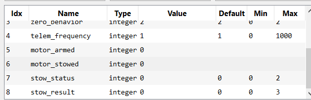
motor_stowed Parameter in DroneCAN GUI Tool
Stow on Disarm
If a Vertiq module supports Advanced Arming, then it is possible to configure its disarming behavior to trigger a stow. This means that when the module transitions from armed to disarmed, it will attempt to move to the stow position. This can be useful for users that want their modules to always be in the stow position when disarmed.
Refer to the Disarming Behavior section for more information on how to configure this behavior and the specifics of how the stow feature interacts with disarming.
Stow on Timeout
Modules that support configurable timeout behavior can set their timeout behavior to trigger a stow. This means that when a timeout occurs, the module will move to its stow position.
Refer to the Timeout Behavior section for more information on how to configure this behavior and the specifics of how the stow feature interacts with timeouts.
Holding Position
Once the module reaches the stow position, it can transition to one of several different behaviors as defined by the Hold Stow parameter. You can read more about this above. The possible behaviors are:
Coast When Stowed: The module will release the stow and coast, allowing itself to spin freely. It will not attempt to hold its stow position.
Hold Stow Angle: The module will attempt to actively hold its stow position using the position controller. This can be useful if you need the module to maintain its stowed position when external forces, such as the wind, are acting on it.
Brake When Stowed: The module will release the stow and brake. The module is not actively attempting to hold its stow position, but brake mode does provide more resistance to moving than coast.
Low Power Hold: The module will attempt to hold its stow target position, but it will swap between brake mode and actively using the position controller to try and move to the stow position depending on how far it is from the stow position. This is described in more detail below.
Low Power Hold
The Low Power Hold behavior is more complex than the other stow ending behaviors and has several configurations of its own. This section describes the Low Power Hold behavior in detail.
Low Power Hold reduces power consumption by switching between brake mode and actively attempting to hold the target position with the position controller depending on how far the module is from the target position. Brake mode consumes relatively little power, but only provides marginal resistance to moving out of position. Actively holding the position with the position controller forces the module back to its target position, but it consumes significantly more power in doing so. So, in Low Power Hold, the module goes into brake mode when it is close to its target position, and switches back to actively moving to the target position when it is too far away from the target. Once the module is again close enough to its target, the module transitions back into brake mode. This reduces overall power consumption by allowing the module to spend more time in brake mode, with its relatively low power consumption, at the cost of allowing more possible error in the position at any given moment.
This transitioning between braking and holding is defined by two configurable parameters: the Low Power Hold Allowed Target Error and the Low Power Hold Max Brake Error.
The Low Power Hold Allowed Target Error defines how close the module needs to be to the target position before transitioning from actively holding the postion to braking. For example, if the Low Power Hold Allowed Target Error is set to 0.025 radians, then if the module is using the position controller to move back to its target position, it will switch to brake mode when it is within 0.025 radians of the target. If this is too small, it can make it difficult for the motor to successfully swap into brake mode from the active hold.
The Low Power Hold Max Brake Error defines how far away from the target position the module can be before transitioning from braking to actively holding the position. For example, if the Low Power Hold Max Brake Error is set to 0.2 radians, then if the module is braking, it will switch to actively holding its position once the error from the target is greater than or equal to 0.2 radians. The module will then actively move back towards its target position until it is within the Low Power Hold Allowed Target Error, at which point it will switch back to braking.
It is important to consider the tradeoff between reduced power consumption and acceptable position error when using this feature. Swapping into brake mode reduces power consumption, but it allows the module to move more easily out of the stow target position, and the Low Power Hold Max Brake Error explicitly defines an acceptable amount of error from the target stow position. Therefore it is important to consider what level of position error is acceptable for any given application, and if no error is acceptable it may be better to use Hold Stow Angle as the stow ending behavior instead.
This process of transitioning back and forth between actively holding the position and braking depending on the module’s error from the target and its current state is summarized in the diagram below.

Low Power Hold State Transition Diagram
The Low Power Hold Max Brake Error should typically always be larger than the Low Power Hold Allowed Target Error. The goal is to have the module move close to its target position when actively holding, and then to allow it to brake over a wider area to reduce power consumption. The diagram below illustrates an example of how these error ranges should generally compare, with the module moving close to its target position to get within the Low Power Hold Allowed Target Error range, and then being allowed to move further from its target when braking with a comparatively larger Low Power Hold Max Brake Error.

Low Power Hold Example Error Comparison
The Low Power Hold Allowed Target Error and Low Power Hold Max Brake Error can be configured from Control Center on the General tab, as shown below.

Low Power Stow Control Center Configurations
Stow Status Reporting
The current stow status and the result of a previous stow attempt are reported by the module. This can be useful for checking if a stow is currently on-going or if the previous stow completed successfully.
Stow Status
The stow status reports on the current state of the stowing feature on the module. When the status is queried, an integer will be returned that indicates the state. Possible states are:
Idle (Stow Status = 0): There is no stowing happening, the stow feature is idle and ready for new commands.
In Progress (Stow Status = 1): A move to the stow position is in progress but the module has not yet reached its stow position.
Holding (Stow Status = 2): The module is attempting to hold its stow position. This applies to both the standard Hold and the Low Power Hold. See the Holding Position section for more information.
The stow status can be queried over IQUART using the “stow_status” entry of the “stow_user_interface” client in the API. It can also be queried over DroneCAN using the “stow_status” configuration parameter, as shown below in the DroneCAN GUI Tool at index 7.

stow_status Parameter in DroneCAN GUI Tool
Stow Result
The stow result reports on how the previous stow attempt ended. When the result is queried, an integer will be returned that indicates the result. Possible results are:
No Result (Stow Result = 0): This indicates that there have been no previous stow attempts to report on. The stow result starts at this result after reboot.
Completed (Stow Result = 1): The previous stow attempt successfully made it to its stow position without issue.
Interrupted (Stow Result = 2): The previous stow attempt was interrupted before completing. See Interrupting Stow for details on stow interruptions.
Error (Stow Result = 3): An unexpected error occurred during the previous stow attempt.
The stow result can be queried over IQUART using the “stow_result” entry of the “stow_user_interface” client in the API. It can also be queried over DroneCAN using the “stow_result” configuration parameter, as shown below in the DroneCAN GUI Tool at index 8.
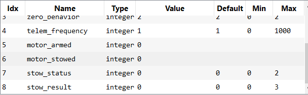
stow_result Parameter in DroneCAN GUI Tool
Interrupting Stow
While a stow is in progress, any received commands that control the spinning state of the module will interrupt the stow. When interrupted, the ongoing stow is canceled and the stow feature is reset so that it will be ready when stow is triggered again. If an interruption occurs, the stow result will reflect that as detailed in the Stow Result section.
Some examples of possible sources of interruption are:
A throttle command when the module is armed
Arming or disarming, see the Armed State Transitions section for possible causes
An IQUART command to spin the motor regardless of armed state, such as setting the “ctrl_volts” of “propeller_motor_control”
The above list of examples is not exhaustive, there are other possible sources of interruption, any command that would affect how the module is moving will interrupt the stow.