PWM and DSHOT Control with a Flight Controller
This tutorial is meant to walk you through the process of performing basic setup and testing of a Vertiq module in order to integrate with a flight controller using Standard PWM or DSHOT. This tutorial covers only the basics of testing that the flight controller can spin your modules with the appropriate protocol, and not the setup of any additional flight controller peripherals like an RC controller or a GPS. This tutorial takes you from a totally fresh module and flight controller to a Standard PWM or DSHOT controllable module through a flight controller.
This tutorial covers setup and testing on ArduCopter using Mission Planner and PX4 using QGroundControl. It covers using both the Standard PWM and DSHOT protocols since each setup process is largely similar. In the places where there are differences, the proper steps for both protocols are explained.
These instructions are applicable to any Vertiq module using speed firmware. Though they have different form factors and some different configuration parameters available, the configuration and setup for basic control with Standard PWM or DSHOT is the same for all Vertiq speed modules. This example uses a Vertiq 81-08 G2 for demonstration purposes, but it is not specific to the 81-08.
Note
If you intend on using DroneCAN and a timer based protocol as redundant sources, please first read Redundant Throttle and Arming in order to fully understand the arming interactions that may occur between the protocols.
Hardware Setup
This example uses a Vertiq 81-08 G2 and a Pixhawk 6C as the flight controller. Since this tutorial is focused specifically on setting up the Vertiq module, the only additional peripheral that is used along with the flight controller is a safety switch.
The module is powered through its XT-60 connector from a bench-top power supply. For more information on how to properly power your module, refer to its family page.
When setting the module’s configuration parameters through the Control Center, it should be connected to a PC with a USB-to-UART converter. For more details on how to use the Control Center with a module, refer to IQ Control Center Manual.
When testing with the flight controller, the module’s pins must be connected to the flight controller’s appropriate output pins. The exact position or labeling of the flight controller’s output pins will vary depending on the specific hardware you are using. Refer to your flight controller’s documentation for more information. Your module’s RX pin should be connected to the flight controller’s signal output pin sending throttle commands. Your module’s ground connection should be connected with the flight controller’s. For information about your module’s RX and GND connections, see the module’s family page. For this specific example using a Pixhawk 6C, the signal pin is I/O PWM OUT (MAIN OUT) 1 for PWM and FMU PWM OUT (AUX OUT) 1 for DSHOT.
Warning
If you are using DSHOT and certain flight controllers, including Pixhawks, you may need to use a different set of outputs than when using Standard PWM. These outputs may be labeled as AUX or FMU PWM. This is because not all outputs on all flight controllers support using DSHOT. See the Mixing ESC Protocols section of the Arducopter DSHOT setup instructions and the PX4 DSHOT documentation for more details. Refer to your flight controller’s documentation for details on what protocols its outputs support.
For more details on the wiring for your module, refer to the module’s family page. In the Communication section of Pinout and Connectors, locate the RX/PWM In pin. This is the PWM/DSHOT input for all Vertiq modules. In general, connection with your module will look as follows:

Warning
- To ensure the safe and reliable operation of this product, all electrical connections must be properly strain-relieved during aircraft assembly. Failure to do so may result in wire fatigue, breakage, or intermittent electrical contact, which can lead to system malfunction or in-flight failure.
Strain Relief Required: All wire harnesses connected to the motor, ESC, or any other component must be secured using appropriate strain relief methods to prevent mechanical stress on solder joints, connectors, and wire insulation.
Bend Radius Consideration: When routing wires, maintain a minimum bend radius appropriate for the wire gauge and insulation type to avoid excessive stress and long-term degradation.
Dynamic Loading: Consider vibration, movement, and thermal cycling in your design to ensure wires are not allowed to flex or tug under operational conditions.
Firmware and Software Versions
This tutorial was tested with IQ Control Center version 1.6.0. It should also be applicable to future versions of the Control Center, but there may be some slight differences in the number of parameters available on tabs or the exact names of parameters and settings. The version of your Control Center can be seen in the Information tab, as shown in the image below. For more information on how to use the Control Center, refer to IQ Control Center Manual.
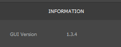
Control Center Version
This tutorial is applicable to all Vertiq modules running speed firmware.
Reverting to Defaults (Optional but Recommended)
If you have previously changed any configurations on the module, it may be useful to revert it to its default state before continuing with this tutorial. This ensures that there will be no lingering conflicts from previous configurations, and this tutorial will work as expected.
To do so, please follow the instructions found at Resetting Your Module to Factory Default Settings.
Module Configuration
Warning
Before setting any parameters, ensure that the module does NOT have a propeller attached and is held in place securely. If the module is unsecured it could move unexpectedly when it starts to spin. This could damage the module, its connectors, or any nearby observers.
Note
If you are unfamiliar with setting parameters through the Control Center, refer to Module Configuration with IQ Control Center before completing this section.
General Tab
First, there are a few parameters to set in the General tab. Not all of the parameters in this tab are important, and only the relevant ones are highlighted here. If a parameter is not mentioned, you can safely leave it at its default. The correct settings and purpose of each parameter is described in detail in the sections below. Most parameters are the same in Standard PWM and DSHOT setups, but ones that differ have sections for both protocols:
Communication
This parameter controls what type of timer based (hobby) protocol(s) the module will listen for. The module is capable of listening to a wide variety of timer based protocols, which can be selected from the drop-down box. Once the module receives a command in its selected timer based protocol, it will only listen for that type of command until power cycled, so you will not be able to connect with Control Center until you power cycle the module. For example, if the module receives a PWM message when it is set to accept them, it will only listen to PWM messages until it is restarted. If left in Autodetect mode, the module listens for all of the supported timer based protocols to try to determine which is in use.
If you would like to see more details about the communication parsing process, please refer to the image found in our timer based protocol documentation.
Depending on the flight controller’s configurations and noise on the communication lines, the module may have difficulty automatically discovering the protocol while using autodetection. In these cases, it is best to set the module to only listen for a specific type of protocol. As such, we will explicitly set the timer based protocol to use in this setup. The proper value for this configuration depends on if you are using Standard PWM or DSHOT:
Standard PWM Setup: Set Communication to Standard PWM to receive Standard PWM messages
DSHOT Setup: Set Communication to DSHOT600 to receive DSHOT messages
The image below shows what the Communication parameter should look like in Control Center for a Standard PWM setup.

Communication Parameter
FC 2D/3D Mode
This parameter tells the module if the flight controller wants it to operate in 2D mode (spinning in one direction) or 3D mode (able to spin in both directions). For more details on these modes and how to configure the module’s spinning behaviors, see the Throttle Commands and Modes section of the Feature Reference Manual. For this tutorial, 2D mode will be used for the sake of simplicity. Set the FC 2D/3D Mode parameter to 2D as shown below.

FC 2D/3D Mode Parameter
Mode
This parameter determines how the module interprets a setpoint command, i.e., what should the module do when receiving a 50% or 100% throttle command? Is that meant to be a fraction of the battery voltage, a specific drive voltage, or a velocity? The list below provides a brief introduction to each of the 3 possible modes:
PWM: This mode means that the module will apply a fraction of the battery voltage as its drive voltage when given a setpoint. For example, if your battery voltage is 20V, and you send a 50% command, then the module will apply a 10V drive voltage.
Despite the similar naming, this mode has nothing to do with using the Standard PWM timer based protocol
Voltage: This mode interprets the commands as a fraction of the Max Volts set in the Tuning tab. So, if your maximum voltage was set at 8V, and you sent a 25% throttle command, the module would apply a drive voltage of 2V.
Velocity: This mode interprets the command as a fraction of the Max Velocity set in the Tuning tab. So, if your maximum velocity was set at 100 rad/s, and you sent a 25% throttle command, the module would try to spin at 25 rad/s.
The meaning of this parameter is covered in greater detail in the Mode, Maximums, and Direction section of the Feature Reference Manual.
For this example, we will put the module in Voltage mode. To do this, set the Mode parameter to Voltage in Control Center, as shown below.

Mode Parameter
Motor Direction
This sets what direction the module considers to be the positive direction for throttle commands from a flight controller. When the Motor Direction parameter is set to either of the 2D directions (2D clockwise or 2D counter clockwise), the module will always spin in the specified direction on a throttle command. For example, if the Motor Direction was set to 2D counter clockwise, the module would always spin counter-clockwise in response to a throttle command. Configuring the direction of the module and mapping throttle commands to directions is covered in greater detail in the Throttle Commands and Modes section of the Feature Reference Manual.
For this example, the module should always spin counter-clockwise. To configure that, set the Motor Direction to 2D counter clockwise in Control Center, as shown below.

Motor Direction Parameter
Tuning Tab
The Tuning tab also has parameters that must be set for this example. Similarly to the General tab, the majority of the parameters on this tab are not relevant for this test setup and can be left at their defaults. The sections below describe important Tuning tab parameters as well as their values for the case of this example. They are the same for both DSHOT and PWM setups.
Max Volts
This parameter determines the maximum drive voltage of the module when operating in Voltage mode. All setpoints will be interpreted as a fraction of this maximum voltage. So if Max Volts is 24V, then a 50% command will drive the module with 12V. To use Voltage mode, this needs to be set to the desired maximum. For safety reasons, Max Volts is set to 10V for this test setup, as shown in the image below. This keeps the speed of the module relatively low. When using the module on an actual drone you will likely want to increase this to match your battery voltage. For more information on this parameter and the modes available on the module, refer to the Mode, Maximums, and Direction section of the Feature Reference Manual.

Max Volts Parameter
Note
If you are using velocity mode rather than the recommended voltage mode, please make sure to set Max Velocity rather than Max Volts to the velocity
the module should spin when given 100% throttle.
Communication Timeout
This determines the length of the module’s communication timeout. If it does not hear any messages within that time, it will timeout and play its timeout song. If this is below 1s, it can be difficult to test with the Control Center. So for this example, the timeout should be set to 1.5s. To do this, set the Timeout parameter to 1.5s, as shown in the image below. Depending on how frequently your flight controller sends throttle commands, you may want to decrease the timeout when using the modules on a drone. For more information on the timeout feature of Vertiq modules, refer to the Timeout section of the Feature Reference Manual.

Timeout Parameter
Testing the Module
Warning
Ensure that the module is secured and there is no propeller attached before performing any testing.
Now that we’ve configured the module to spin given a flight controller’s commands, we will use the Vertiq Testing Tool (VTT) to verify that our module reacts how we expect. If you have not installed or used VTT, please do so before continuing with this tutorial.
Connect your module to VTT, and confirm that you are in the ESC Input tab (seen in the top left corner). Now, verify that your module’s settings match what you expect given the tutorial so far.
Note
Older versions of Vertiq firmware may have a default arming throttle upper limit of 7.5% rather than the 12.5% illustrated here.

If these settings are incorrect, or you would like to adjust any, you can do so directly through VTT.
In the bottom right corner, you’ll see the ESC Input slide bar.
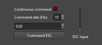
The ESC Input here simulates a throttle sent through a flight controller. Using IQUART, it transmits throttle commands as a value from zero to one just as a flight controller may send a PWM pulse of 1000 to 2000 microseconds.
Once again, please ensure that all propellers are removed at this point before attempting to spin your module.
We’ll use the Continuous command option to have VTT send throttles automatically at the frequency specified by the Command rate (by default 10 Hz). Make sure that the throttle is at 0% to ensure that the throttle command is within our arming region, and click the Continuous command box.

You should hear your module play its arming song after 1 second (10 Hz to reach 10 arming throttles). With your module armed, you can move the ESC Input slide bar up and down to adjust your module’s speed. Feel free to use VTT’s plotting interface to watch any parameters you would like while the module spins.
In the following video example, you’ll see a basic demo of the module arming with Continuous command enabled and then spinning at the throttle specified.
Note
You can find another full module configuration example for Velocity mode at Example Module Flight Controller Configuration and ESC Testing with the Control Center.
The next two sections cover setting up ardupilot and PX4 flight control firmwares. Please ensure that you are in the correct section for your flight control firmware before attempting to follow the instructions.
Ardupilot and Mission Planner Configuration and Testing
Note
If you are using PX4 firmware, please follow the PX4 and QGroundControl Configuration and Testing tutorial.
Please review the ArduPilot First Time Setup guide if this is your first time setting up ArduPilot with your flight controller. This tutorial was tested using Mission Planner 1.3.80 and ArduCopter v4.5.5, as shown in the figure below. These instructions assume you are starting from the default ArduPilot parameters, and cover how to test that the flight controller and module can communicate with no additional flight controller peripherals. See the Hardware Setup section for more details on the hardware and connections.
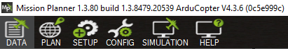
Mission Planner and Arducopter Version
In order to reset your flight controller to default settings with Mission Planner, navigate to “Config,” open “Full Parameter List,” and on the right side, locate Reset to Default outlined in red below. Click this, and then follow the directions on the windows that appear.

Setting Frame Type
The first step is to provide ArduCopter with a frame type. On a fully assembled drone, this should match the drone’s physical layout, but for this test the specific frame you set is unimportant. To set the frame type, select “Setup” from the top bar in Mission Planner, and then expand “Mandatory Hardware” on the sidebar. Select “Frame Type,” and a frame selection screen should appear. This tutorial was tested with the “X” quadcopter frame, under the first frame option, as shown below.
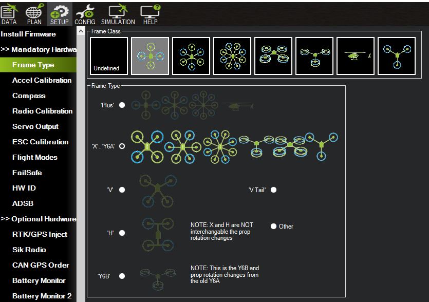
Mission Planner Frame Type Selection
Setting ArduCopter PWM Parameters
Note
This section is only relevant if you want to use the Standard PWM protocol to control the modules. Otherwise, continue to Setting ArduCopter DSHOT Parameters below
There are several parameters that need to be set properly to make sure the flight controller can communicate with the module using Standard PWM. Connect to your flight controller with Mission Planner, select “Config” from the top toolbar, and then select “Full Parameter List” from the sidebar. On the right of the parameter list is a search box you can use to search for each parameter. Confirm that the following parameters are set to the proper values and change them if necessary:
MOT_PWM_TYPE = 0
This selects the output PWM Type. 0 sets it to standard PWM. See the ArduCopter documentation for more details.
MOT_PWM_MAX = 2000
This sets the max PWM value in microseconds that will be output to the module. By default, Vertiq modules use a range of 1000us to 2000us with Standard PWM.
MOT_PWM_MIN = 990
This sets the minimum PWM value in microseconds that will be output to the module. By default, Vertiq modules use a range of 1000us to 2000us with Standard PWM, but setting this to 990us helps ensure the module will not spin on a 0% throttle.
SERVO_DSHOT_ESC = 0
This disables DSHOT commands. These settings cover a setup using Standard PWM, so DSHOT should be disabled.
Reboot your flight controller to make sure the new parameters take effect. The important parameters and their proper values in the Mission Planner parameter list are shown in the figure below.
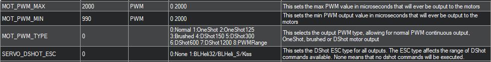
Important ArduCopter Standard PWM Parameters in Mission Planner
Setting ArduCopter DSHOT Parameters
Note
This section should only be used if you want to use the DSHOT protocol to control the modules. Otherwise, use Setting ArduCopter PWM Parameters above.
ArduCopter needs to be configured properly to use DSHOT as its protocol for controlling the modules. To set these parameters, connect to your flight controller and select “Full Parameter List” under the “Config” section of Mission Planner. Search for the parameters listed below and make sure they are set to the appropriate values:
MOT_PWM_TYPE = 6
This selects the output PWM Type. 6 sets it to DSHOT600. See the ArduCopter documentation for more details.
SERVO_DSHOT_ESC = 0
This controls what type of additional ESC commands will be sent from the flight controller. These additional commands include things like beeping, LED control, and other potentially useful but non-essential extra commands that can be sent over DSHOT. This does not need to be enabled in order to send the module throttle commands over DSHOT, so we are leaving it disabled for simplicity. See the ArduCopter documentation for more details.
SERVO_DSHOT_RATE = 0
This sets the output rate for DSHOT outputs. Leaving it at 0 leaves the output rate at 1 kHz. See the ArduCopter documentation for more details.
Reboot your flight controller to make sure the new parameters take effect. The important parameters and their proper values in the Mission Planner parameter list are shown in the figure below.
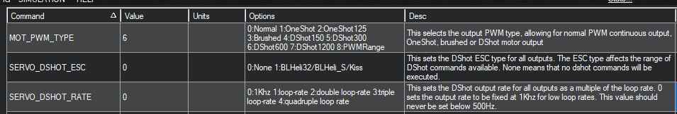
Important ArduCopter DSHOT Parameters in Mission Planner
Re-Configuring ArduCopter DSHOT Outputs
Note
Only needed on some flight controllers, see the ArduCopter and PX4 documentation for more details on which
Depending on the type of flight controller hardware you have, you may need to re-configure which outputs you are using to a DSHOT compatible pin. The reason for this and the types of flight controllers it affects are discussed in Mixing ESC Protocols and in this Ardupilot forum post. This issue applies to the Pixhawk 6C that was used for this tutorial, and also applies to the popular Cube Orange flight controller.
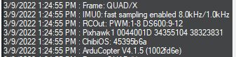
For affected flight controllers, their main outputs can transmit PWM, but not DSHOT. One way to check for this issue is to check the “Messages” section of the “Data” tab in Mission Planner on reboot. This will display what kinds of protocols are actually going to be output on each pin based on the configuration. Set your flight controller for DSHOT as discussed above, reboot it, connect to it, and check the “Messages” section. If you see a message like the one below that lists “RCOut: PWM 1-12,” that means your flight controller outputs will still only output PWM, and you must connect the module to a DSHOT compatible output instead.
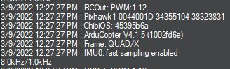
Message Showing Outputs are PWM Only
For the Pixhawk used to test this example, the module is connected with FMU PWM OUT (AUX OUT) 1. Exactly which pins to use and how they are labeled will vary depending on your flight controller. Refer to the flight controller’s documentation for more information.
Next, you need to tell ArduCopter to use AUX OUT 1 (or the equivalent pin on your flight controller) as the output for Motor 1 on your vehicle. ArduCopter uses SERVOX_FUNCTION variables to assign a function to each output. For the Pixhawk, AUX OUT 1 is controlled by SERVO9_FUNCTION. Set SERVO9_FUNCTION = 33 to output the throttle commands for Motor 1 on AUX OUT 1. See the ArduCopter documentation for details on what settings to use for different functions. The figure below shows the proper setting for this parameter to assign DSHOT to AUX OUT 1 on the Pixhawk 6C.
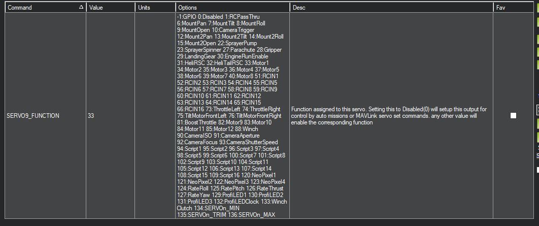
Setting AUX OUT 1 as the Motor 1 Output
Reboot the flight controller and connect to it again. This time in the “Messages” section you should see that RCOUT also has DS600 on its outputs, as shown below.
Message Showing Outputs Are Using DSHOT
Configuring the Safety Switch
By default, ArduCopter will not allow you to test spinning your modules unless a safety switch attached to your flight controller is armed. If you have a safety switch connected to your flight controller, then you can move on to testing the module. If you do not have a safety switch but would still like to test your modules, this section will cover how to override the requirement for a safety switch.
The ArduCopter documentation provides details on how to configure the safety switch. To disable the switch, Set BRD_SAFETY_DEFLT (also called BRD_SAFETYENABLE on older firmwares) to 0. The image below shows BRD_SAFETY_DEFLT set to this value in Mission Planner. If your module is powered on and attached to the flight controller when you change this parameter, you may hear the module arm. That is because the flight controller will begin sending 0% throttle commands on its outputs once this is changed.

Disabling the Safety Switch with the BRD_SAFETY_DEFLT Parameter
Testing the Module with Mission Planner
Warning
Double check that the module is secured and there is no propeller attached before performing any testing.
Now we can use Mission Planner’s built-in motor testing tools to make sure the flight controller can control the module.
Start with the module powered off, but connected to the flight controller.
Select “Setup” from the top toolbar, and then expand “Optional Hardware” on the sidebar.
Select “Motor Test” from the “Optional Hardware” options. See the image below as an example of what the Motor Test screen should look like at this point.
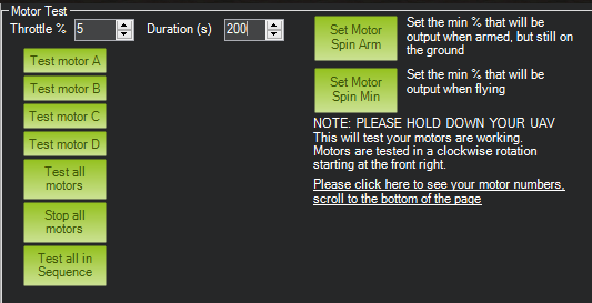
Motor Test Screen in Mission Planner
Power on the module and wait for it to complete its startup song.
If you have disabled the safety switch and are using Standard PWM, the module should play its arming song after startup when attached to the flight controller.
Arm your safety switch if you have one.
If using Standard PWM, the module should play its two tone arming song as the flight controller starts sending 0% throttle commands once the safety switch is armed
On DSHOT, the module will not arm yet.
Set the “Throttle %” to 5% and the “Duration” to 5s, and click “Test All Motors”.
The module should spin slowly for 5 seconds, and then stop.
On Standard PWM, the module will spin and stop without any additional arming or disarming noises
On DSHOT, the module will arm when you send the command, spin for the duration, and then stop and disarm again, since DSHOT sends a specific disarm command at the end of the test.
Try some other throttle levels to see the module running at different speeds.
For DSHOT, you cannot command a high throttle level immediately as the module will disarm after each command, and only re-arms on a throttle command close to 0%. So for DSHOT testing, increase the duration and send a low level throttle command to arm the module, and before that command ends and the module disarms, send another higher throttle command.
See the Successful Actuator Test section below for a video of this whole process. It demonstrates what sounds you should expect to hear from the module, as well as the module successfully spinning with Arducopter and Mission Planner.
PX4 and QGroundControl Configuration and Testing
Note
If you are using Ardupilot firmware, please follow the Ardupilot and Mission Planner Configuration and Testing tutorial.
This tutorial was tested using QGroundControl 4.3.0 and PX4 version 1.14.3, as shown in the figures below. These instructions assume you are starting from default parameters, and cover how to test that the flight controller and module can communicate with no additional flight controller peripherals. See the Hardware Setup section for more details on the hardware and connections.
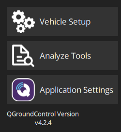
QGroundControl Software Version Used for This Tutorial
PX4 Firmware Version Used for This Tutorial
Setting Frame Type
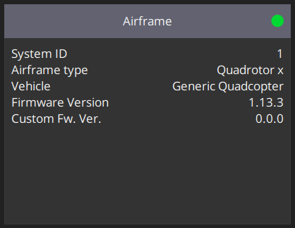
The first step is to choose an airframe. Normally, this would be determined by the layout of your vehicle, but with only a single module, the exact airframe used isn’t particularly important. For simplicity, this tutorial uses a Generic x Quadcopter, as shown in the figure below. To setup the airframe in QGroundControl follow the steps below.
Click on the QGroundControl logo in the upper left of the interface, and select “Vehicle Setup”.
Select “Airframe” from the sidebar.
Scroll through the airframes until you find “Quadrotor x”. Leave this set to “Generic Quadcopter”, and click on the “Quadrotor x” box. It should be highlighted in yellow.
Scroll back up and hit “Apply and Restart”.
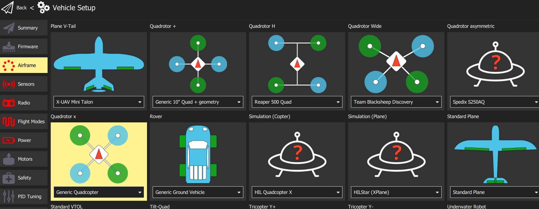
QGroundControl Airframe Setup
Note
Make sure that the module directions are correctly set for your airframe. In QGroundControl, a blue motor represents counter clockwise. For example, if you are using the Generic Quadcopter, your front right and back left modules should generally be configured to 2D counter-clockwise, and your front left and back right should be 2D clockwise.
Setting PX4 PWM Parameters
Several parameters must be set properly to make sure the flight controller can communicate with your module using PWM. Connect to your flight controller with QGroundControl, and under “Vehicle Setup” select “Actuators.” On the Actuators tab, you will see the following.

Select PWM MAIN. Here, you can assign each channel output with the motor it represents in the drone geometry as well as the protocol to be used on the channels. For this example, we will assign MAIN 1 to Motor 1 using the PWM 400 Hz protocol. PX4’s Disarmed, Minimum, and Maximum parameters define the protocol specific values that are transmitted when your flight controller is both disarmed and armed. When using PWM, each value represents a number of microseconds. So, for example, suppose Disarmed is set to 990, Minimum to 1000, and Maximum to 2000. When the flight controller is in a disarmed state, it will transmit a 990us pulse on the channel being configured. Once armed, the flight controller will begin outputting active throttles where the pulses will never be less than 1000us and will never exceed 2000us.
Warning
It is strongly encouraged that your Minimum throttle output from the flight controller lies outside of your module’s disarming region. If your module disarms while in flight, it can cause your modules to stop responding to throttle commands until they rearm. For the safest flight experience, your flight controller’s outputs and your module’s arming regions must align such that the flight controller will never disarm your module via throttles while the flight controller is armed.
In the module configuration completed so far in this tutorial, there is no configured disarming region. So, we will set our Disarmed output to 1000us and our Minimum output to 1005us. Note that our Disarmed output should always be lower than the Minimum output. The Maximum value can remain 2000us.
Once you have fully configured the output channel, you will see sliders appear under Actuator Testing. Please note that if your module is powered on and connected to the MAIN 1 output when it is enabled, you will hear the module play its two tone arming song as PX4 begins transmitting Disarmed throttle commands (1000us) immediately on channel activation. By default, Vertiq modules take 0% throttle commands as arming throttles.
For more information on how to configure the module to properly interpret throttle commands, see the Throttle Commands and Modes section of the Feature Reference Manual. For more information on arming and disarming the module, refer to the Advanced Arming section of the Feature Reference Manual.

Now reboot your flight controller to ensure that all changes take effect.
Your flight controller and single module are now ready for testing. In order to add more PWM outputs, simply set the other MAIN outputs to the correct motor output, and ensure each channel is using the PWM 400 Hz protocol.
Tip
Optional Advanced Configuration Example
So far in this tutorial, we have performed a basic configuration that allows your module to arm and get spinning, but does not configure module disarming. It is possible to configure your flight controller and module to disarm in specific throttle regions as discussed in the arming manual.
For example, suppose your module is configured to disarm on throttle commands between 0 and 2%, and to arm between 2 and 12.5%. When the flight controller is disarmed, we want our module to be as well. Since Vertiq modules use a range of 1000us to 2000us for PWM throttle parsing, we can easily map our percentages to the correct Disarmed, Minimum, and Maximum values. When disarmed, we want the flight controller to output a command that will disarm the module. So, we will set our Disarmed value to 1000us as it represents a 0% throttle. Now, we want to ensure the module arms when the flight controller does, so we’ll adjust our minimum flight controller output to fall inside of our arming region. To ensure we fall inside of the arming region, we will configure the flight controller to output a 2.5% throttle once armed. 2.5% of our 1000us range is 25, so we’ll set our Minimum to 1025us. The maximum is defined by the longest pulse Vertiq modules accept as PWM throttles, 2000us.
The disarming example provided here differs from the configuration covered previously in this tutorial. It is only meant to illustrate a possible set of configurations that could be used to integrate disarming into this basic example.
Setting PX4 DSHOT Parameters
Several parameters must be set properly to make sure the flight controller can communicate with your module using DSHOT. Connect to your flight controller with QGroundControl, and under “Vehicle Setup” select “Actuators.” On the Actuators tab, you will see the following.
Select PWM AUX. Here, you can assign each channel output with the motor it represents in the drone geometry as well as the protocol to be used on the channels. For this example, we will assign AUX 1 to Motor 1 using the DSHOT600 protocol. Once activated, you will see sliders appear under Actuator Testing in the bottom left.
Note
According to PX4’s documentation, DSHOT cannot be transmitted via your flight controller’s MAIN outputs. These may also be labeled I/O PWM OUT depending on your flight controller. You’ll notice that on the PWM MAIN tab, DSHOT is not an option. DSHOT can only be transmitted through your flight controllers AUX (FMU PWM OUT) output channels.


Now reboot your flight controller to ensure that all changes take effect.
Your flight controller and single module are now ready for testing. In order to add more DSHOT outputs, simply set the other AUX outputs to the correct motor output, and ensure each channel is using the DSHOT600 protocol.
Testing the Module with QGroundControl
Warning
Double check that the module is secured and there is no propeller attached before performing any testing.
Now we can use the motor testing tools in QGroundControl to confirm that the flight controller can control the module.
Power off the module, and connect it to the flight controller.
In QGroundControl under “Vehicle Setup,” select the “Actuators” section.
Arm the safety switch on your flight controller if necessary.
Turn on the module, and wait for it to complete the 5-beep startup song.
Enable the module sliders with the toggle underneath the sliders.
Move the Motor 1 slider bar just slightly above its start position to give the module a throttle command near 0%. The module should play its two tone arming song, and may spin slowly.
Actuator Testing for PWM and DSHOT¶ 
Actuator Testing when using DSHOT

Actuator Testing when using PWM
Note
All Actuator Testing is subject to the Advanced Arming feature. As such, when using DSHOT, halting the Actuator Test will send an explicit disarm command, and the module will stop and disarm. In order to re-arm, you must transmit throttle commands within your arming region. By default, placing the slider near the bottom should arm your module. When using PWM, your module will not disarm unless you have configured disarming on throttle. This is because PX4 is constantly sending PWM commands at the defined disarmed value, so no timeout will occur.
Move the Motor 1 slider around, and observe how the module changes speed.
Successful Actuator Test
The following demonstrates successfully using PX4’s actuator test to drive a single Vertiq module through DSHOT. The module has been configured as described in Module Configuration. This example uses a Vertiq 81-08 G2 85Kv, and shows all steps from module startup to the explicitly set DSHOT disarm command.