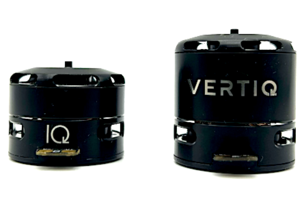
Vertiq 23-XX Family
Size |
Kv |
Default Firmware |
Available Firmware |
|---|---|---|---|
23-06 |
220 |
Servo |
Servo |
23-06 |
2200 |
Speed |
Speed, Pulsing |
23-14 |
920 |
Speed |
Speed |
Hardware Setup Walkthrough
What’s in the Box
Every Vertiq 23-XX module is packaged with the following:
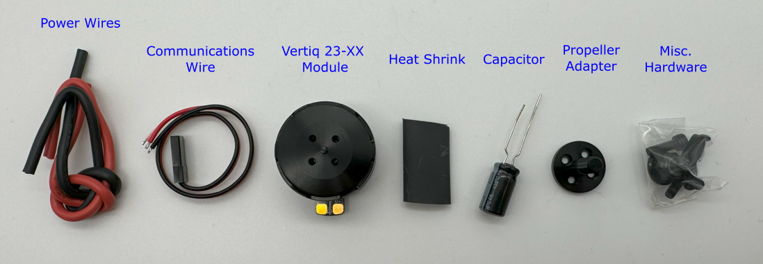
Vertiq 23-XX Family in the Box
1 Vertiq 23-XX module
1 propeller adapter
1 bag of hardware containing
4 M2x6 bolts
4 M3x8 bolts
1 M5x0.8 locknut
1 communications wire
1 set of power wires
1 270uF capacitor
1 length of heat shrink
If you are missing any components, please contact us at support@vertiq.co.
Note
The exact color(s) of the provided hardware may differ based on supplier availability.
Pinout and Connectors
The Vertiq 23-XX family does not support any connectors, and only accepts direct soldering to the exposed pads.
More information about your module’s electrical characteristics and connections can be found in the datasheet provided below.
Note
It is highly recommended for your and your module’s safety that you shroud all connections with the supplied heat shrink.
Warning
- To ensure the safe and reliable operation of this product, all electrical connections must be properly strain-relieved during aircraft assembly. Failure to do so may result in wire fatigue, breakage, or intermittent electrical contact, which can lead to system malfunction or in-flight failure.
Strain Relief Required: All wire harnesses connected to the motor, ESC, or any other component must be secured using appropriate strain relief methods to prevent mechanical stress on solder joints, connectors, and wire insulation.
Bend Radius Consideration: When routing wires, maintain a minimum bend radius appropriate for the wire gauge and insulation type to avoid excessive stress and long-term degradation.
Dynamic Loading: Consider vibration, movement, and thermal cycling in your design to ensure wires are not allowed to flex or tug under operational conditions.
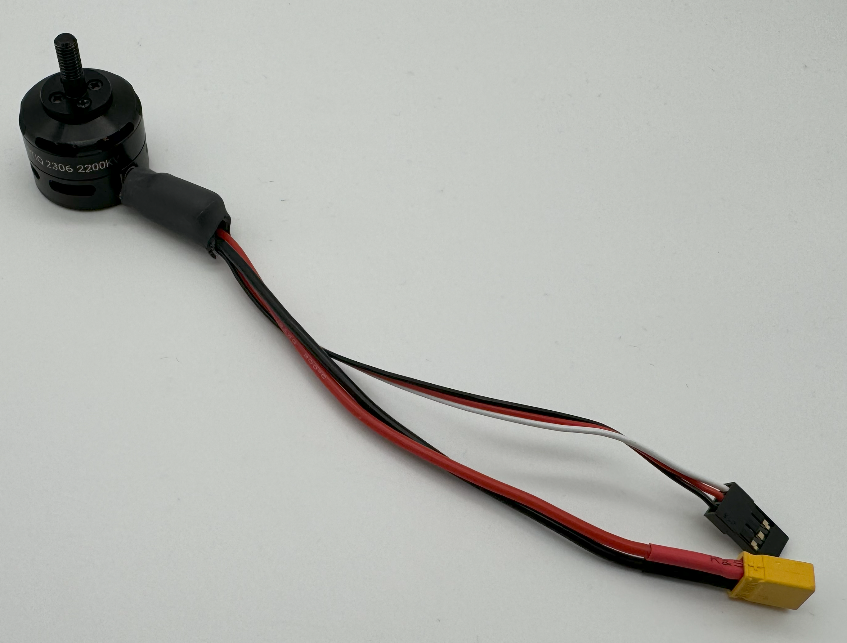
Final 23-XX Connections with Heatshrink
Power
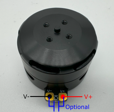
23-XX Power Connections
All Vertiq 23-XX modules support a minimum of 5.4V and a maximum of 6S power (25.2V) across the power terminals for operation.
Note
If you are driving your Vertiq 23-XX module(s) at a low voltage or near the maximum operating voltage, it is recommended that you connect the provided 270uF capacitor between the power terminals. If you are unsure whether you should or should not include the capacitor, it is safest to include it. You may need to shorten the capacitor’s leads in order to solder it properly.
A module with its power lines and capacitor attached should look as follows
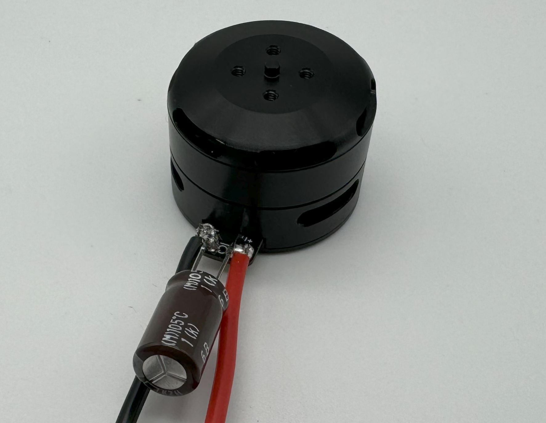
23-XX Power Connections with Capacitor
Communication - IQUART or Timer Based Protocol Configuration
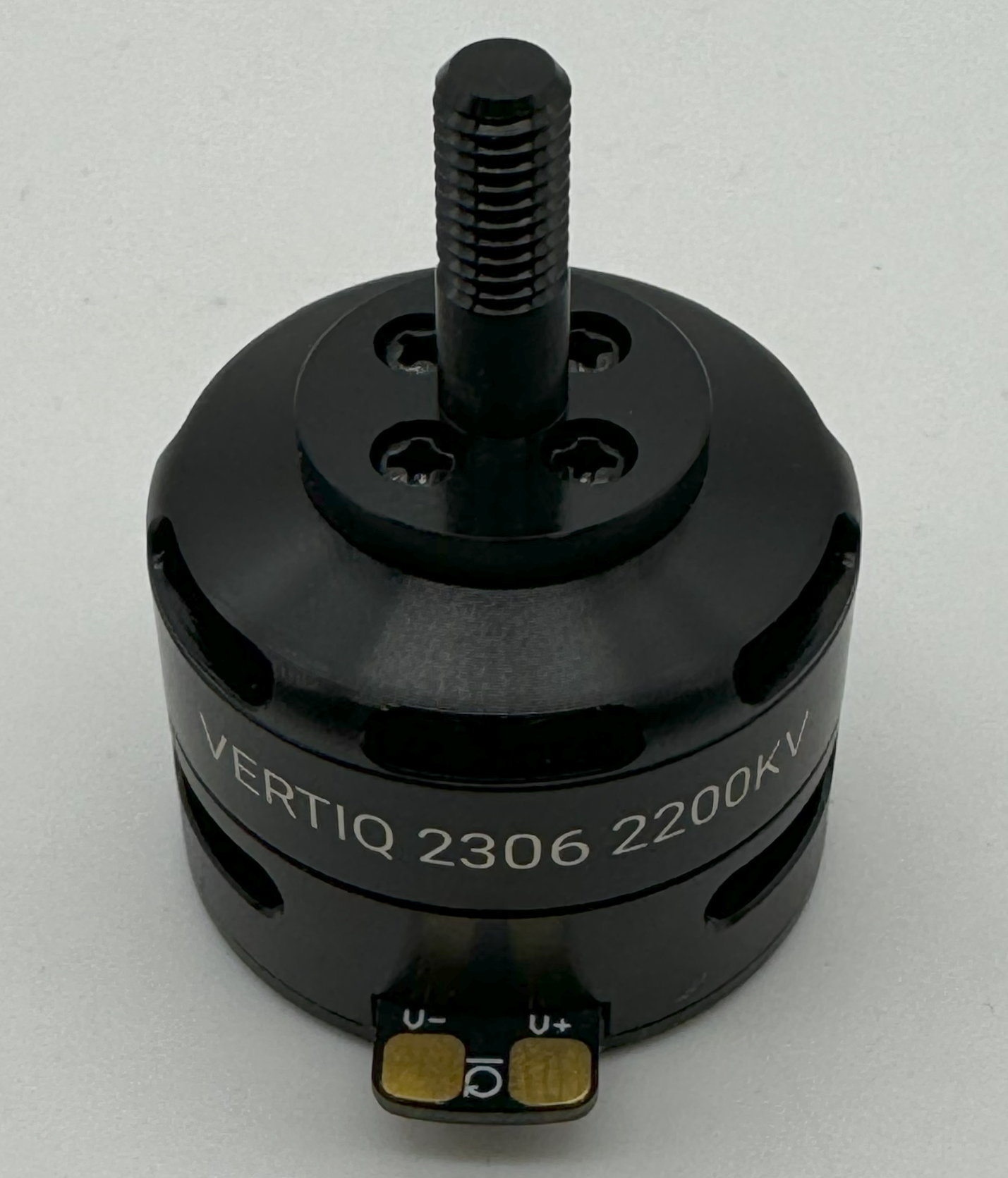
23-XX Communication Connections
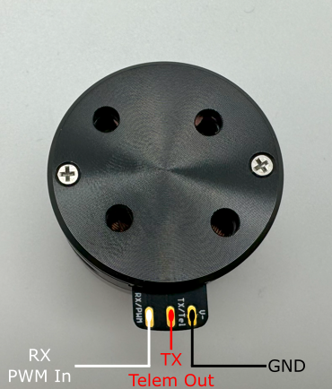
In order to use either IQUART or any Timer Based Protocols you will have to connect the supplied communication wire to your module. In any scenario, please ensure that the TX line of your module is connected to your controller’s RX line, and the RX line of your module is connected to your controller’s TX line.
Please note that in order to configure your module through the IQ Control Center, to communicate with your module with any of our APIs, or to complete any firmware updates you must connect communication wires as each of these uses IQUART communication.
Adding the communication wires to your module results in the following
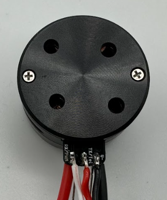
23-XX Communication Connections Soldered
Attaching a Propeller for Flight
In order to attach a propeller, first find the propeller adapter and M2 bolts from the provided hardware.
Note
For your safety, it is highly recommended that you apply a threadlocker, like Loctite 243, to each screw used to affix your propeller to your module.
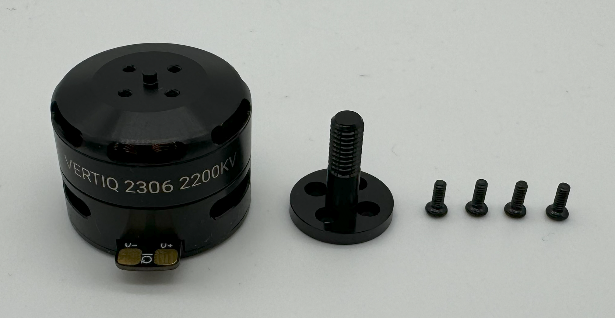
23-XX Propeller Adapter Hardware
Use the bolts to connect the adapter to the module
23-XX with Propeller Adapter Hardware
Now, find the locknut from the provided hardware as well as the propeller you plan on using.
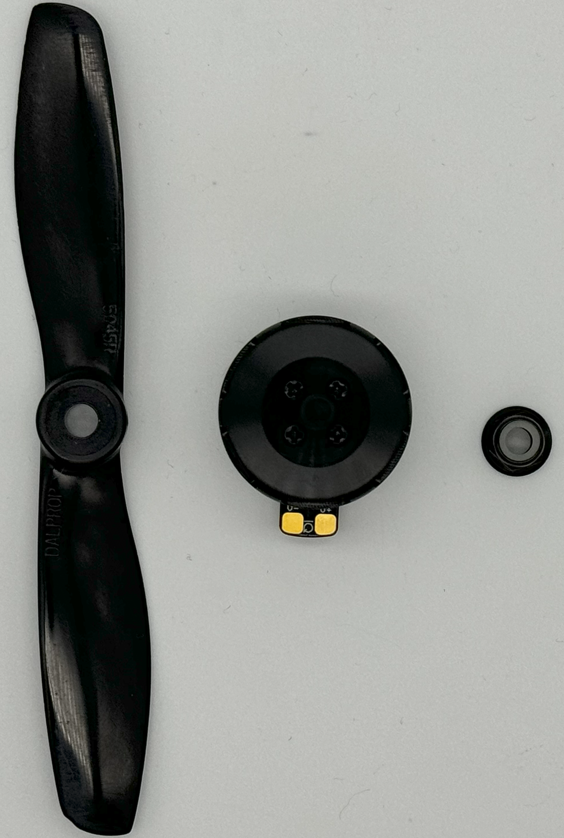
23-XX with Propeller Hardware
Place the propeller on the module, tighten the locknut to secure it, and your module is ready to fly.
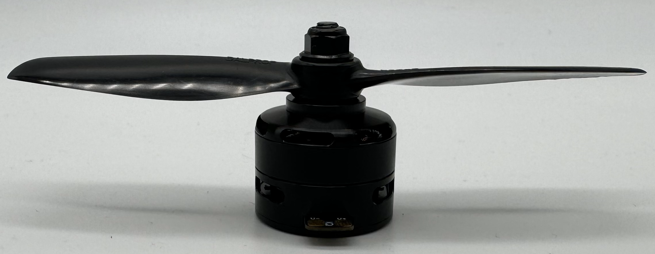
23-XX with Propeller
Warning
Please remove the propeller before performing any startup procedures and Getting Started manuals. Failure to do so can be dangerous. Only attach propellers when your modules will be in flight, and all surroundings have been cleared.
Next Steps
Now that you have successfully wired your module for use, feel free to complete the Getting Started Guide for your module and its firmware style.
Additional Mechanical/Electrical Information
Number of pole pairs - 7
For more information about the Vertiq 23-XX family’s mechanical and electrical characteristics please visit the correct datasheet for your module using the links below
Changing or Updating Firmware
Please follow the instructions found in Updating Firmware with the Control Center
More Information
Once you have completed the proper “Getting Started Guide,” you can begin to dive deeper into your module’s capabilities. To learn about all of the features supported by your module, please review our supported features table.