GPIO Controller
Module Support
The user GPIO interface is supported by only the Fortiq-42 modules.
Description
Vertiq’s GPIO interface provides a flexible method of interacting with a module’s user-specific GPIO pins. Each GPIO can be set to input or output, which can be switched on-the-fly, if desired. Each pin set as an input may choose whether or not to use an internal pull resistor (up or down), as well as the type of pull used. Each pin set as an output may choose whether to output in a Push-Pull or Open-Drain configuration.
All pins set as an input can read the input value, and all pins set to output can read, write, and save the outgoing value. Access to these behaviors is available through registered or addressable methods. Both registered and addressable interactions occur via IQUART commands, and will be covered more below. Vertiq’s GPIO interface has flexibility to change any GPIO parameter via the registered or addressable format. Any savable value set through the IQ Control Center will be stored in the module’s persistent memory, and will be retained through resets and power-cycles. Using Vertiq’s Python API, values can be written, saved, and read.
Registered GPIO Access
The GPIO registers encode each bit to one GPIO (ex. bit 3 corresponds with GPIO3). All registers excluding the Input Values (read only) have Read/Write/Save permissions.
Note
The number of GPIOs available is dependent on the module in use. See your module’s documentation to learn more. Setting values to GPIOs that do not exist on your module will have no effect.
As an example, suppose your motor has 3 user accessible GPIOs. To set all 3 to outputs using Push-Pull configuration and output high on only GPIO 3:
Set GPIO Mode to 7
Set PP/OD to 0
Set Output Values to 4
The GPIO registers are summarized below:
GPIO Registers¶ Register Name
Bit 7
Bit 6
Bit 5
Bit 4
Bit 3
Bit 2
Bit 1
Bit 0
Access
Description
GPIO Mode
GPIO 8 Mode
GPIO 7 Mode
GPIO 6 Mode
GPIO 5 Mode
GPIO 4 Mode
GPIO 3 Mode
GPIO 2 Mode
GPIO 1 Mode
R/W/S
Sets the GPIO pin to a specified mode, input or output. 0 indicates input, 1 indicates output
Input Values
GPIO 8 Input
GPIO 7 Input
GPIO 6 Input
GPIO 5 Input
GPIO 4 Input
GPIO 3 Input
GPIO 2 Input
GPIO1 Input
RO
A read only value that indicates the value of each input pin when set to input mode
Output Values
GPIO 8 Ouput
GPIO 7 Ouput
GPIO 6 Ouput
GPIO 5 Ouput
GPIO 4 Ouput
GPIO 3 Ouput
GPIO 2 Ouput
GPIO 1 Ouput
R/W/S
The value to send/being sent on an output GPIO line
Use Pull
GPIO 8 Use Pull
GPIO 7 Use Pull
GPIO 6 Use Pull
GPIO 5 Use Pull
GPIO 4 Use Pull
GPIO 3 Use Pull
GPIO 2 Use Pull
GPIO 1 Use Pull
R/W/S
Determines whether or not to use the internal pull-up or pull-down resistor on input mode. If 0, use no pull, if 1 use the pull type specified by the corresponding Pull Type bit
Pull Type
GPIO 8 Pull Type
GPIO 7 Pull Type
GPIO 6 Pull Type
GPIO 5 Pull Type
GPIO 4 Pull Type
GPIO 3 Pull Type
GPIO 2 Pull Type
GPIO 1 Pull Type
R/W/S
Determines the type to use on an input pin, if Use Pull is set high. 0 indicates pull down, 1 indicates pull up.
PP/OD
GPIO 8 PP/OD
GPIO 7 PP/OD
GPIO 6 PP/OD
GPIO 5 PP/OD
GPIO 4 PP/OD
GPIO 3 PP/OD
GPIO 2 PP/OD
GPIO 1 PP/OD
R/W/S
Determines the output mode, push-pull or open-drain. 0 indicates push-pull, 1 indicates open-drain
Addressable GPIO Access
User GPIOs allow for individual write access to each GPIO. Addressable access is a write only protocol. To set a value via addressable access, send one byte that represents the value to write as well as the GPIO to write to. The MSB represents the value, while the bottom 7 bits represent the GPIO number. For example, to set GPIO 3 to be an output, write 13110 (0b10000011) to the GPIO Addressable - Mode entry (see Initial GPIO Setup and Testing with IQ Control Center)
Bit 7 |
Bit 6 |
Bit 5 |
Bit 4 |
Bit 3 |
Bit 2 |
Bit 1 |
Bit 0 |
|---|---|---|---|---|---|---|---|
Value to Set |
Target GPIO Number 1 to your modules top-most GPIO Number |
||||||
Usage
Initial GPIO Setup and Testing with IQ Control Center
The IQ Control Center provides the easiest way to interact with your module’s GPIO peripherals. To do so:
Open IQ Control Center. If you have not installed the program, please follow the instructions in Getting Started with Speed Motors Using IQ Control Center.
Connect your module to IQ Control Center
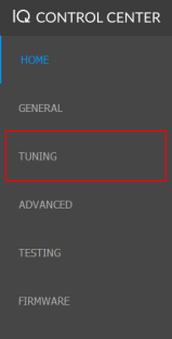
Select the Tuning Tab on the left side
Scroll down in the Tuning Tab until you find GPIO Addressable - Mode
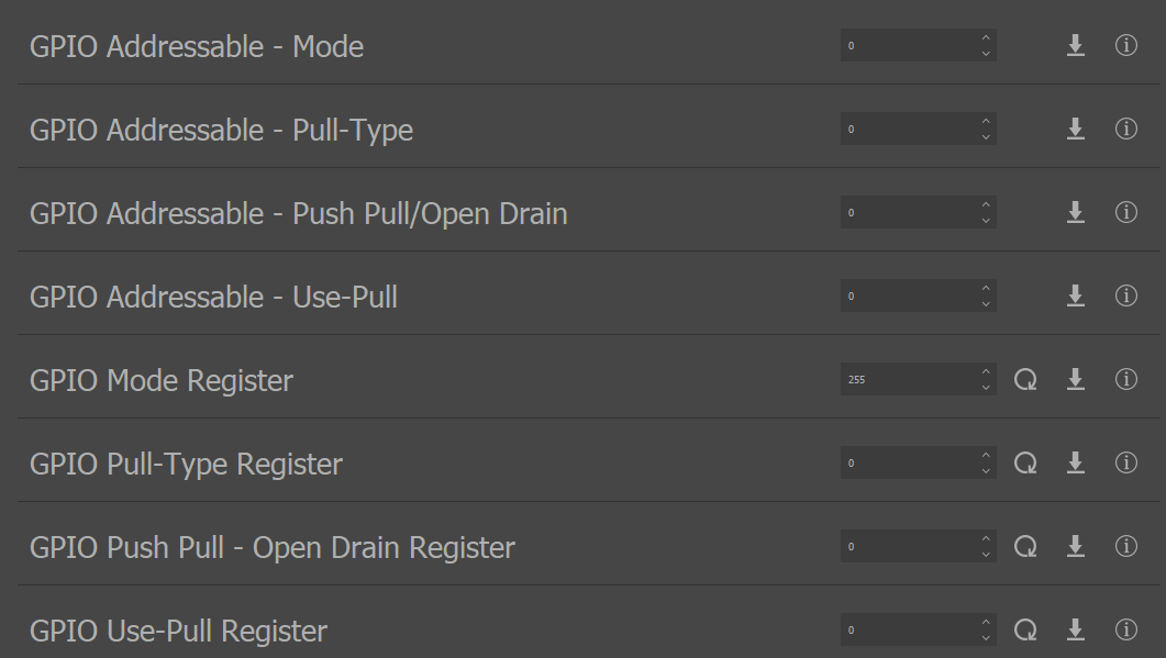
This is where you will find access to both registered and addressable GPIO control. In order to read the current GPIO state, you must read from the register values, as addressable access is Write-Only.
To test your GPIOs:
Create the following circuit

Write 7 to GPIO Mode Register to set all 3 GPIOs to output
Make sure GPIO Push Pull - Open Drain Register is set to 0, indicating that all outputs are configured as push-pull
Open the Testing Tab in the Control Center, and find GPIO Addressable - Output
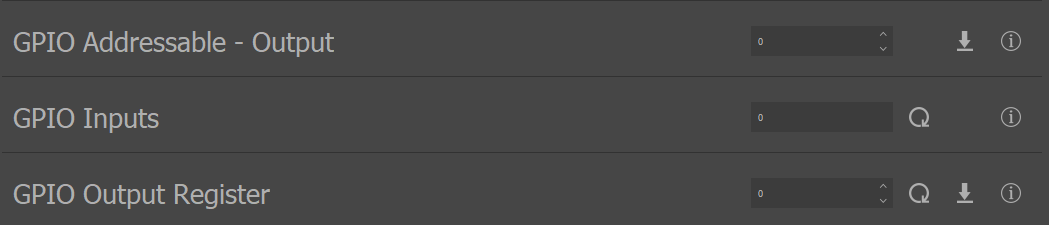
Write 7 to GPIO Output Register to set all outputs high. You should see your LEDs light up
Write 1 to GPIO Addressable - Output to turn off only GPIO 1
Write 6 to GPIO Mode Register to set GPIO 1 to input and GPIOs 2 and 3 to output
Write 129 to GPIO Addressable - Use-Pull to enable pull on GPIO 1
Write 129 to GPIO Addressable - Pull-Type to set GPIO 1 to pull up
Select the Update Button on GPIO Inputs. You should read 1
Write 6 to GPIO Pull-Type Register to set GPIO1 to pull down. You should now read 0 on GPIO Inputs
Vertiq Python API - GPIO Interface
Note
Please note that the following GPIO Interface testing was performed with a Fortiq-42 module. Your exact commands may change depending on the module in use.
The GPIO interface can also be used through Vertiq’s Python API. To use the API, please use the following steps:
If you have never used Vertiq’s Python API, you must first set up your local computer to use the Python API using the instructions found at Getting Started with Python
After completing the walkthrough, you can interact with the gpio_controller client
To read a value
print(fortiq.get("gpio_controller", "<entry_name>"))
For example, to read the value stored in the modes_register:
print(fortiq.get("gpio_controller", "modes_register"))
To write a value
fortiq.set("gpio_controller", "<entry_name>", value)
For example, to set the bottom three GPIOs to outputs
fortiq.set("gpio_controller", "modes_register", 7)
To save a value to persistent memory
fortiq.save("gpio_controller", "<entry_name>")
For example, to save the value in the modes_register
fortiq.save("gpio_controller", "modes_register")