Advanced Arming
Vertiq modules can support an advanced arming feature. The advanced arming feature allows users to control the module’s armed state either manually or with throttle commands. It also allows users to configure specific behaviors to occur on armed state transitions. Modules will not react to throttle messages until they have armed, providing improved safety. The configurable behaviors on armed state transitions allow users to easily integrate advanced behaviors into their setup just by controlling the throttle messages they send, simplifying flight controller integration.
The Module Support section below details which Vertiq modules currently support advanced arming.
Note
If your module does not support the redundant throttle feature, please also read the Legacy Arming Support section for additional constraints on the advanced arming feature. You can find if your module’s firmware supports redundant throttle on its family page.
Module Support
To see if your module and firmware style supports this feature, please see our supported features table.
Armed States
Modules can be in one of two armed states at any time:
Armed: In this state, the module will spin when it receives a throttle command. It is unsafe to be near an armed module with an attached propeller.
Disarmed: In this state, the module will NOT spin when it receives a throttle command. If using IQUART to control the module it is still possible that the module can be commanded to spin by other commands, such as by setting the “ctrl_volts” of the Propeller Motor Controller client. As such, if you are using IQUART messages alongside the typical throttle commands to control the motor you should approach it with caution even when it is disarmed.
The process of transitioning between armed states is covered in the Armed State Transitions section.
Reboot Armed State
After a reboot, regardless of what armed state the motor was in previously, it will start up in the disarmed state. Users must transition the motor from disarmed to armed to begin spinning again following a reboot.
Armed State Transitions
Note
If your module does not support the redundant throttle feature, please also read the Legacy Arming Support section for additional constraints on the advanced arming feature. You can find if your module’s firmware supports redundant throttle on its family page.
There are two types of armed state transitions:
Arming: A transition from disarmed to armed. See Arming Behavior for more details on what occurs during and after an arming transition.
Disarming: A transition from armed to disarmed. See Disarming Behavior for more details on what occurs during and after a disarming transition.
There are multiple ways to trigger armed state transitions covered in the sections below.
Throttle Regions
It is possible to transition between armed states using only the throttle commands sent to the module. This can be accomplished by specifying arming throttle regions and disarming throttle regions.
A throttle region is a range of throttle commands specified by an upper bound and a lower bound. Any throttle command that falls within that range or on one of the boundaries is considered to be in that throttle region. Throttle commands that are in the arming throttle region will contribute towards transitioning the module to the armed state, and throttle commands that are in the disarming throttle region contribute towards transitioning the module to the disarmed state.
Arming With the Arming Throttle Regions
Arming Throttle Region Definition
The arming throttle region is specified by two parameters: Arm Throttle Upper Limit and Arm Throttle Lower Limit. These two parameters can be found in the IQ Control Center under the General tab, as shown below. Users can configure these to specify any range of throttle commands as the arming throttle region. When a sufficient number of throttle commands in the arming throttle region are received, an arming transition will occur. For more details on the number of arming throttle commands required to trigger an arming transition, see Consecutive Arming Throttles. When the arming transition occurs, the module will perform its arming behavior as detailed in Arming Behavior.
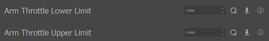
Arming Throttle Region Limits in IQ Control Center
The Arm Throttle Upper Limit defines the upper, more positive bound of the arming throttle region. It should always be more positive than or equal to the Arm Throttle Lower Limit. The Arm Throttle Lower Limit defines the lower bound of the arming throttle region. Every throttle command the module receives in this region is considered an arming throttle and will contribute towards an arming transition. The number of arming throttles required to cause an arming transition is determined by the Consecutive Arming Throttles to Arm parameter as discussed in the Consecutive Arming Throttles section below.
The image below illustrates where the arming throttle region would be for an example setup where the Arm Throttle Upper Limit is set to 0.3 and the Arm Throttle Lower Limit is set to 0.1. Any throttle command between 10% and 30% is an arming throttle.
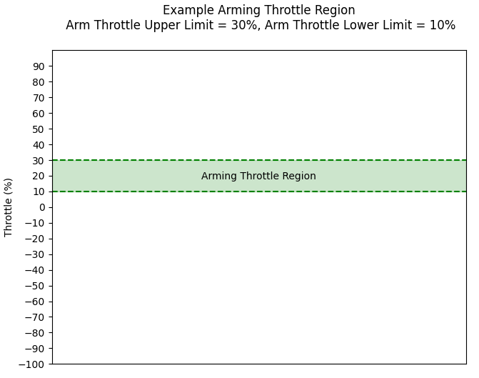
Example Arming Throttle Region
There is a separate parameter that determines whether the arming throttle region exists at all. The Arm On Throttle parameter, shown below in IQ Control Center, allows users to toggle the arming throttle region on or off completely. If this parameter is set to Do Not Arm on Throttle, then there is no arming throttle region and throttles cannot cause an arming transition. Otherwise, arming throttles can be used as previously described.

Arm on Throttle Parameter in IQ Control Center
Consecutive Arming Throttles
Note
If your module does not support the redundant throttle feature, please also read the Legacy Arming Support section for additional constraints on the advanced arming feature. You can find if your module’s firmware supports redundant throttle on its family page.
Users can specify the number of consecutively received arming throttles required to cause an arming transition. This can be useful if the module is in a high-noise situation where there is a danger of noise being interpreted as a throttle command, or as a general safety feature to help prevent unintentional arming.
The number of consecutive arming throttles the module must receive in the arming throttle region to trigger an arming transition can be configured in the General tab of the Control Center with the Consecutive Arming Throttles to Arm parameter, as shown below.

Consecutive Arming Throttles to Arm Parameter in IQ Control Center
Note that the number of consecutive arming throttles received by the module resets whenever a throttle command outside of the arming throttle region is received. The module must receive the specified number of consecutive arming throttles all in a row, with no throttle commands outside of the arming throttle region coming in between them. For example, if the module’s Consecutive Arming Throttles to Arm parameter was set to 10, and it received 9 throttle commands in the arming throttle region, 1 outside of the region, and finally 1 throttle command in the region, the module would not arm. At the end of that sequence, the module has only received 1 consecutive arming throttle because the throttle command from outside of the arming region reset the count.
To summarize, the module must receive a user-configurable number of consecutive throttle commands, all in the arming throttle region, to trigger an arming transition.
Arming with Throttle Example
An example of a possible arming setup and procedure is outlined below.
For this example, assume that the Arm On Throttle parameter is set to Arm On Throttle, the Arm Throttle Upper Limit is set to 0.15, the Arm Throttle Lower Limit is set to 0.0, and Consecutive Arming Throttles to Arm is set to 10. The figures below show what these settings look like in the IQ Control Center when applied to a module.

Arm on Throttle and Arming Throttle Region Limits for Example
Consecutive Arming Throttles to Arm for Arming Example
An illustration of the arming throttle region defined by these parameters is shown below to demonstrate what throttle commands will be considered arming throttles.
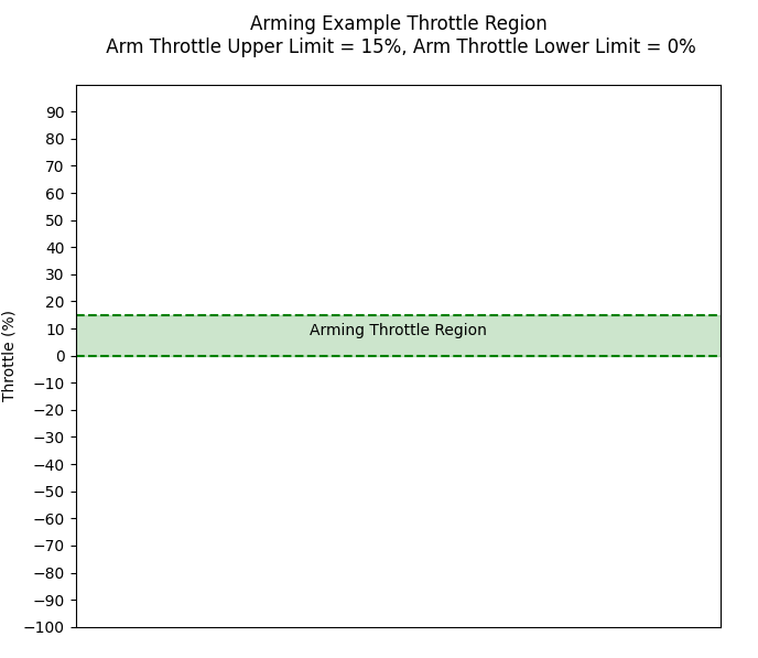
Throttle Region Illustration for Arming Example
Now that the module is properly configured, we can begin sending throttle commands to it. The module is in the disarmed state initially.
Imagine that we begin sending 30% throttle commands to the module. Nothing will happen in this case, and the module will not spin and it will not arm. The module is disarmed, so throttle commands will not cause it to spin. These 30% throttle commands are outside the arming throttle region, so they will not cause the module to arm.
If we switch to sending -10% throttle commands, we can expect the same result. The module is still disarmed, and -10% is not in the arming throttle region.
Now, if we begin sending 5% throttle commands, the commands fall within the arming throttle region, and will be counted as arming throttles. The module will not begin an arming transition when it receives the first 5% throttle command however, as our Consecutive Arming Throttles to Arm parameter means that it must receive 10 consecutive arming throttles before it will arm. After 10 consecutively received 5% throttle commands, the module will begin an arming transition. When the module arms, it will perform its arming behavior, as detailed in Arming Behavior.
Disarming With the Disarming Throttle Region
Note
If your module does not support the redundant throttle feature, please also read the Legacy Arming Support section for additional constraints on the advanced arming feature. You can find if your module’s firmware supports redundant throttle on its family page.
Disarming Throttle Region Definition
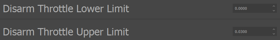
The disarming throttle region is specified by two parameters: Disarm Throttle Upper Limit and Disarm Throttle Lower Limit. These two parameters can be found in the IQ Control Center under the General tab, as shown below. Users can configure these to specify any range of throttle commands as the disarming throttle region. When a throttle command in the disarming throttle region is received, a disarming transition will occur. For more information on what exactly the module does when a disarming transition occurs, see the Disarming Behavior section.
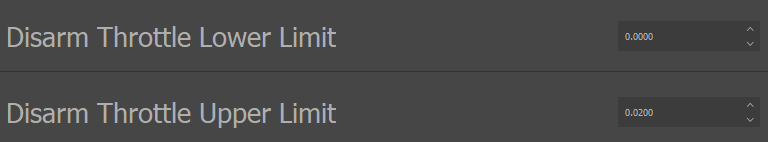
Disarming Throttle Region Limits in IQ Control Center
The Disarm Throttle Upper Limit defines the upper, more positive bound of the disarming throttle region. It should always be more positive than or equal to the Disarm Throttle Lower Limit. The Disarm Throttle Lower Limit defines the lower bound of the disarming throttle region. Any throttle command the module receives in this region is considered a disarming throttle and will cause a disarming transition. Like with arming throttles, there is a Consecutive Disarming Throttles to Disarm parameter that allows users to select how many throttles in the disarming region should trigger the disarming behavior.
The image below illustrates where the disarming throttle region would be for an example setup where the Disarm Throttle Upper Limit is set to 0.15 and the Disarm Throttle Lower Limit is set to 0.0. Any throttle command between 0% and 15% is a disarming throttle in this setup.
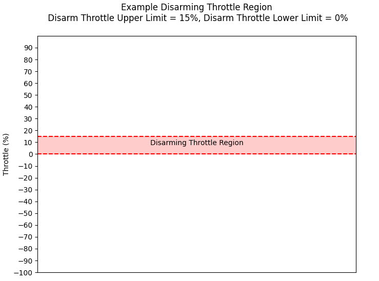
Example Disarming Throttle Region
There is a separate parameter that determines whether the disarming throttle region exists at all. The *Disarm On Throttle* parameter, shown below in IQ Control Center, allows users to toggle the disarming throttle region on or off completely. If this parameter is set to Do Not Disarm on Throttle, then there is no disarming throttle region and throttles cannot cause an disarming transition. Otherwise, disarming throttles can be used as previously described.

Disarm on Throttle Parameter in IQ Control Center
Disarming with Throttle Example
An example of a possible disarming setup and procedure is outlined below.
For this example, assume that the Disarm On Throttle parameter is set to Disarm On Throttle, the Disarm Throttle Upper Limit is set to 0.10, and the Disarm Throttle Lower Limit is set to 0.0. The figures below show what these settings look like in the IQ Control Center when applied to a module.
Disarm on Throttle Parameter Example Setup in IQ Control Center
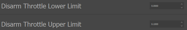
Disarm Throttle Regions Example Setup in IQ Control Center
An illustration of the disarming throttle region defined by these parameters is shown below to demonstrate what throttles will be considered disarming throttles.
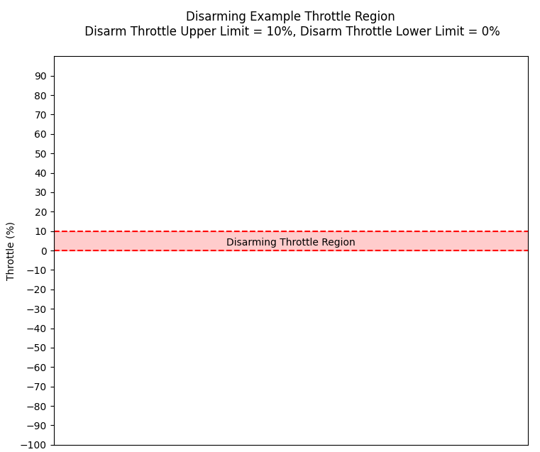
Disarming Example Throttle Region
Now that the module is properly configured we can begin sending throttle commands to it. Assume that the module is already in the armed state.
Imagine that we begin sending 15% throttle commands to the module. Because the module is armed, it will spin at 15%, but the module’s arming state will be unaffected. These 15% throttle commands are outside the disarming throttle region, so they will not cause the module to disarm.
If we switch to sending -5% throttle commands, we can expect a similar result. The module will spin in the opposite direction and more slowly than when sending the 15% throttle commands, but its armed state will not change.
If we instead begin sending 5% throttle commands, those commands will fall within the disarming throttle region, so they are counted as disarming throttles. When enough of these 5% throttle commands are received as defined by Consecutive Disarming Throttles to Disarm, the module will immediately begin a disarming transition. For more details on what the behavior of the module will be during the disarming transition, refer to the Disarming Behavior section.
Throttle Region Overlap
Depending on the module’s configuration, it is possible for the arming and disarming throttle regions to overlap. In this case, the disarming throttle region will take precedence, and throttles in the overlapping region will be considered as disarming throttles.
The following example illustrates this behavior. In the video, you’ll see the arming and disarming throttle upper limits shown in purple and green respectively. Both lower limits are set to 0. This means that between 0 and 0.05, the two regions overlap. You’ll see the user start raising throttle in the bottom right hand side, and you’ll see that the armed state (in white) does not become armed until the throttle is above 0.05. This is where we exit the overlapping region, and arming throttles apply. Then, you’ll see that the module disarms immediately when the throttle input hits 0.05. This is because the disarming region will always win out over the arming region when they overlap.
User Commands
Note
If your module does not support the redundant throttle feature, please also read the Legacy Arming Support section for additional constraints on the advanced arming feature. You can find if your module’s firmware supports redundant throttle on its family page.
It is possible for users to manually trigger arming and disarming transitions over DroneCAN and IQUART. This approach is generally more difficult to integrate with flight controllers as it requires modifying them to send the arm and disarm commands at the appropriate times, but it is possible for advanced users.
DroneCAN
The “motor_armed” configuration parameter can be used to query and control the module’s armed state over DroneCAN. Setting this parameter to 0 will trigger a disarming transition, and setting it to 1 will trigger an arming transition. Note that disarming has no effect if you are already disarmed, and arming has no effect if you are already armed. Getting from this parameter will report the current armed state, 0 for disarmed and 1 for armed.
The appearance of this parameter in the DroneCAN GUI Tool is shown below.
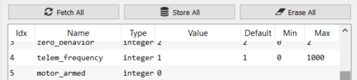
motor_armed Parameter in DroneCAN GUI Tool
IQUART
The “motor_armed” entry of the “arming_handler” client in the API can be used to manually trigger arming and disarming transitions over IQUART. Setting this entry to 0 will trigger a disarming transition, and setting it to 1 will trigger an arming transition. Note that disarming has no effect if you are already disarmed, and arming has no effect if you are already armed. Getting from this entry will report the current armed state, 0 for disarmed and 1 for armed.
This functionality is also exposed in the Advanced tab of the IQ Control Center through the Arming State parameter as shown below. This entry can be used to check on the current armed state or manually transition the state as needed.

Arming State Parameter in IQ Control Center
DSHOT Disarm
The DSHOT hobby protocol reserves one of its special values for commanding a disarm. Vertiq modules support this command. Whether or not the module will disarm on reception of this message is determined by the value of the allow_dshot_disarming_message parameter. If it is true, the module will perform a disarming transition on reception. If it is false, the disarming command is ignored. By default, this parameter is true.
Disabling the DSHOT disarming command can be especially useful when leveraging redundant throttle inputs as it can help avoid arming loops while disarming/arming on throttle.
Arming with DroneCAN ArmingStatus
Vertiq modules that support DroneCAN’s ArmingStatus message can use the message to control their arming state. You can find more information about this in our DroneCAN documentation. If you are using DroneCAN to control your module, we highly recommend using this method of controlling your module’s arming state and disabling throttle based arming transitions.
Timeout
Communication timeouts can be configured to result in multiple options in regards to arming. You can read about these options in our timeout documentation.
Please note that by default, timeouts will always trigger a disarming transition. If the module is armed just before a timeout occurs, it will be disarmed just after the timeout.
Always Armed
Note
If your module does not support the redundant throttle feature, please also read the Legacy Arming Support section for additional constraints on the advanced arming feature. You can find if your module’s firmware supports redundant throttle on its family page.
For users who want to avoid any arming procedure altogether, there is the Always Armed parameter. This parameter allows users to specify that they want the motor to immediately arm on the first throttle message it receives, regardless of its value. This parameter can be found in the Advanced tab of IQ Control Center as shown below.

Always Armed Parameter in IQ Control Center
When this parameter is set to the Always Armed value, the first throttle command received will cause the module to immediately arm.
It is recommended to avoid using this feature and to leave this parameter set to Normal Arming whenever possible. Arming on any throttle message may lead to the module arming on high percentage throttles and suddenly spinning rapidly, posing a risk to anyone nearby. Using arming throttle regions as described in Throttle Regions is generally safer, as the module can be set to only arm on low percentage throttles, mitigating the risk that an unexpected arm might pose.
Arming Behavior
When an arming transition (from disarmed to armed) occurs, the module executes its arming behavior. The arming behavior has only one configuration parameter. If
the arming handler’s play_arming_song_on_arm parameter is true, the module will play the arming song, which consists of 2 short, high-pitched notes. The end of this song indicates the module is armed. The module will then begin spinning
at the throttle percentage commanded by its last throttle command, and will begin accepting new throttle commands.
If play_arming_song_on_arm is set to false, however, the module will not play its arming song on arming. Once it receives the correct criteria required to arm,
the module will begin accepting new throttle commands without any audio feedback.
You can access this parameter through the Control Center’s Advanced tab as Play Arming Song on Arm:

Disarming Behavior
Vertiq modules’ disarming process attempts to safely stop the module, and clearly indicate that the disarm procedure is complete. The disarming process consists of 3 basic steps: The module switches how it is driving itself in order to try and come to a stop, plays its disarm song as specified by its playback option, and switches to its final drive state. How the module tries to come to a stop, how many times it plays the disarm song, and what final state it ends up in after playing the song are all configurable by the user.
The image below summarizes this process and the options available at each stage. In the stopping state, the module will set itself to either coast, actively try to stop the module by driving it with 0V, or start a stow. When the module is stopped, the disarm song will play according to its playback option. After the song finishes, the motor will either coast, brake, or execute whatever final behavior is specified by the stow feature. Each of these stages and the options at each stage are shown in the image below.
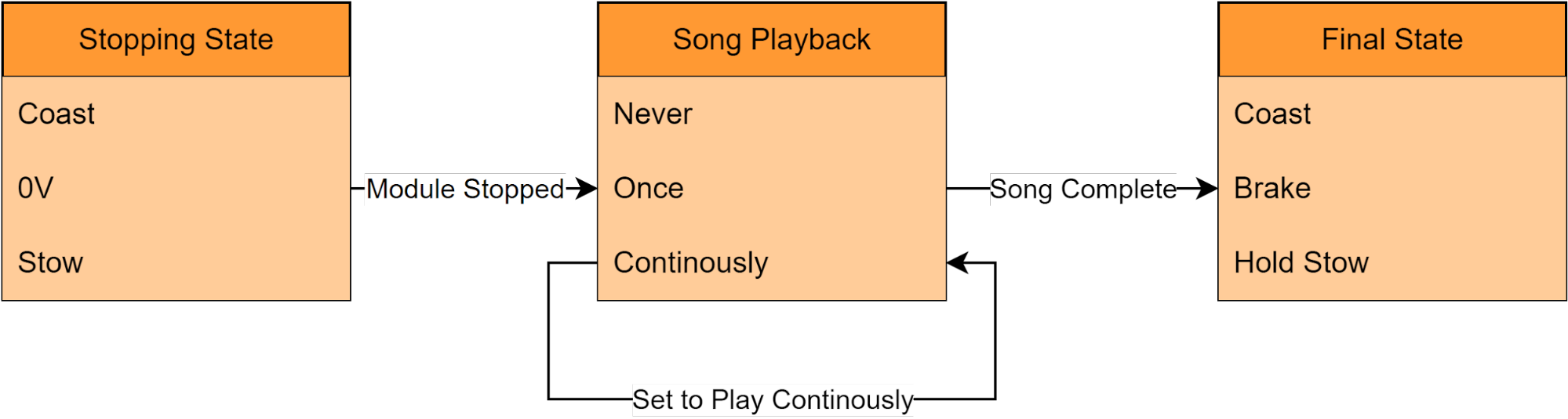
Summary of Disarming Process and Options
Note that not every combination of the options is possible, e.g. stopping with coast and then ending up in a final state of brake is not an option. The Disarming Behavior Options section below provides more details on what combinations are possible and how to configure the behavior.
Disarming Behavior Options
The disarming behavior determines how the module will try to come to a stop and what that final drive mode will be. There are 4 options:
Coast: The module will coast itself when it begins disarming. This means it will spin freely and let drag and friction slow it down. After the song, its final state will be to remain coasting.
0V to Coast: The module will drive itself to 0V when it begins disarming, actively trying to come to rapid stop. After the song, its final state will be to coast.
0V to Brake: The module will drive itself to 0V when it begins disarming, actively trying to come to rapid stop. After the song, its final state will be to brake.
Stow: The module will trigger a move to the stow position when it begins disarming. After the song, its final state will be determined by whatever the stow position feature is configured to do after completing a stow.
Coast to Stow: The module will coast itself when it begins disarming. After the song, the module will trigger a move to the stow position, and its final state will be determined by whatever the stow position feature is configured to do after completing a stow.
Coast to Brake: The module will coast itself when it begins disarming. After the song, its final state will be to brake.
0V to Stow: The module will drive itself to 0V when it begins disarming, actively trying to come to rapid stop. After the song, the module will trigger a move to the stow position, and its final state will be determined by whatever the stow position feature is configured to do after completing a stow.
These options can all be configured through IQ Control Center through the Disarm Behavior parameter, as shown below.

Disarm Behavior Parameter in IQ Control Center
Disarming Song Playback Options
The disarming song playback option determines if and how many times the module will play its disarm song after coming to a stop. There are 3 options:
Never Play: This option will skip the disarm song entirely. The disarm song will never play, and after stopping the module will transition directly to its final state.
Play Once: The disarm song will play once, and then the module will transition to its final state.
Play Continuously: The disarm song will play continuously until the module is armed again or commanded to spin without arming through IQUART. The module will never transition to its final state, as the song will never finish. For example, if the disarm behavior were set to 0V to Brake, the module would apply 0V until stopped, and then play the song forever, it will never brake as part of the disarming process.
These options can all be configured through IQ Control Center through the Disarm Song Playback Option parameter, as shown below.

Disarm Song Playback Option Parameter in Control Center
Arming Configuration with DroneCAN
The parameters and behaviors described in the preceding sections can be configured using DroneCAN GetSet messages. The specific arming parameters available over DroneCAN are:
These parameters are visible in using the DroneCAN GUI below:

For more information about DroneCAN parameters, please see Configuration Parameters.
Flight Controller Integration Examples
The examples below cover the arming specific setup steps on a Vertiq module and a PX4 based flight controller to control arming and disarming with only throttle commands. Using throttle regions for arming and disarming is recommended when integrating with flight controllers, as it allows for the simplest integration.
These examples cover only the additional setup needed to support arming and assume the mode, direction and unit maximums are already set appropriately on the module. For examples of the initial setup of a Vertiq module see the Getting Started with Vertiq’s Speed Firmware with IQ Control Center tutorial and the PWM and DSHOT Control with a Flight Controller tutorial. For information on setting up the mode and throttle configurations for a Vertiq module, see the Throttle Commands and Modes section.
Arming and Disarming with Timer Based Protocols on PWM and PX4
This example covers one way to set up a Vertiq module and a PX4 flight controller sending Standard PWM commands to properly arm and disarm in sync with each other using arming and disarming throttle regions. This assumes that the flight controller and the Vertiq module are set up to use standard, non-reversible Standard PWM commands, where 1000 microseconds commands 0% throttle in the module’s specified direction and 2000 microseconds commands 100% throttle in that same direction.
Module Setup
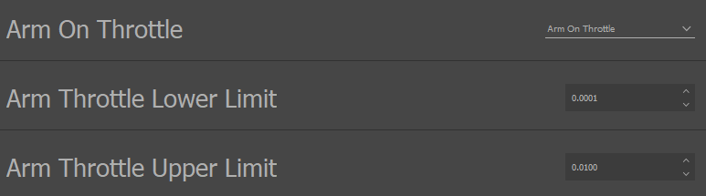
First, configure the arming throttle region on the Vertiq module. To do this, ensure that Arm on Throttle is set to Arm on Throttle in the Control Center, to turn on the arming throttle region. Then, set the Arm Throttle Upper Limit to 0.03 and the Arm Throttle Lower Limit to 0.01. This means that any throttle command between 1% and 3% will be treated as an arming throttle. Finally, set the Consecutive Arming Throttles to Arm to 10, so the module is less likely to arm unintentionally if there is noise on the PWM lines. These configurations are all shown below in the IQ Control Center.
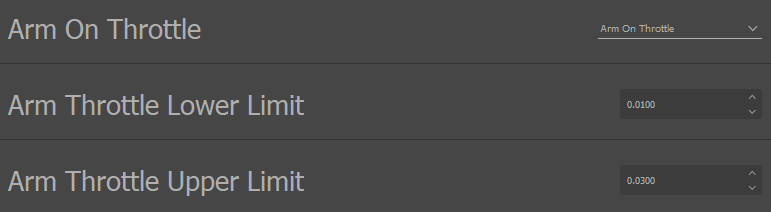
Arming Throttle Region in IQ Control Center

Consecutive Arming Throttles in IQ Control Center
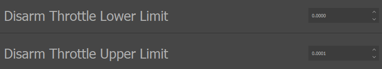
Next, set up the disarming throttle region. This setup is very similar to the setup for the arming throttle region. Disarm on Throttle should be set to Disarm on Throttle, Disarm Throttle Lower Limit should be set to 0.00, and Disarm Throttle Upper Limit should be set to 0.01. Any throttle command from 0% to 1% will be considered a disarming throttle. These configurations are shown below in the IQ Control Center.

Disarm on Throttle in IQ Control Center
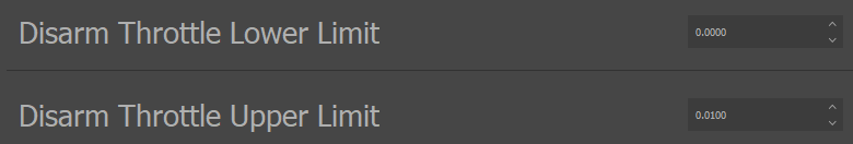
Disarming Throttle Region Boundaries in IQ Control Center
Finally, the disarm behavior should be configured appropriately as well. For this example, set the Disarm Behavior to Coast and the Disarm Song Playback Option to Play Once. Other choices would also work, these are just simple settings to begin with. These configurations are shown below in the IQ Control Center.

Disarm Behavior in IQ Control Center

Disarm Song Playback Option in IQ Control Center
Power off the Vertiq module and move onto configuring the flight controller.
Flight Controller Setup
This example assumes the flight controller is already configured to use Standard PWM commands, and only covers how specifically to adjust the ranges of those commands to match the module’s throttle regions. For more details on how to set up a flight controller, see the PWM and DSHOT Control with a Flight Controller tutorial.
On a PX4 flight controller, it is possible to set the PWM value that will be sent when the flight controller is disarmed and the minimum that will be sent when the flight controller is armed. Adjusting these limits to match what we set on the module will keep the arming status of the flight controller and module in sync.
The important parameters in PX4 to change are PWM_MAIN_DISARM and PWM_MAIN_MIN. Set PWM_MAIN_DISARM to 1005 us, so that when disarmed the throttle command will be in the middle of the 0% to 1% disarming throttle region. Set PWM_MAIN_MIN to 1020 us, so the minimum throttle command when armed will be in the middle of the 1% to 3% arming throttle region. These settings can be seen in the image below taken from QGroundControl.
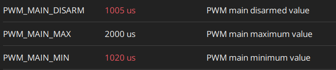
Disarm and Minimum Armed Throttle Command Settings in QGroundControl
Now when the flight controller arms, the module should also arm, and when the flight controller disarms, the module should disarm.
Arming and Disarming with DroneCAN and PX4
This example covers one way to set up a Vertiq module and a PX4 flight controller sending DroneCAN commands to properly arm and disarm in sync with each other using arming and disarming throttle regions.
Module Setup
First, configure the arming throttle region on the Vertiq module. To do this, ensure that Arm on Throttle is set to Arm on Throttle in the Control Center, to turn on the arming throttle region. Then, set the Arm Throttle Upper Limit to 0.01 and the Arm Throttle Lower Limit to 0.0001. This means that any throttle command between .01% and 1% will be treated as an arming throttle. This may seem like a strange throttle region to select, but by default PX4 sends a RawCommand with a value of 0 when disarmed, and a minimum RawCommand of 1 when armed, which translates into a 0.012% minimum throttle command when armed. So this throttle region allows the module to use the default range of the flight controller for arming and disarming.
Set the Consecutive Arming Throttles to Arm to 10, so the module is less likely to arm unintentionally if there is any electrical noise. These configurations are all shown below in the IQ Control Center.
Arming Throttle Region Setup in IQ Control Center

Consecutive Arming Throttles Setup in IQ Control Center
Next, set up the disarming throttle region. This setup is very similar to the setup for the arming throttle region. Disarm on Throttle should be set to Disarm on Throttle, Disarm Throttle Lower Limit should be set to 0.00, and Disarm Throttle Upper Limit should be set to 0.0001. Any throttle command from 0% to .01% will be considered a disarming throttle. Since PX4 sends a 0% throttle command over DroneCAN when disarmed by default, this should work without any additional configuration on the flight controller. These configurations are shown below in the IQ Control Center.

Disarm on Throttle in IQ Control Center
Disarming Throttle Region Boundaries in IQ Control Center
Finally, the disarm behavior should be configured appropriately as well. For this example, set the Disarm Behavior to Coast and the Disarm Song Playback Option to Play Once. Other choices would also work, these are just simple settings to begin with. These configurations are shown below in the IQ Control Center.
Disarm Behavior in IQ Control Center
Disarm Song Playback Option in IQ Control Center
It is also important to ensure that the module is not set to use arming bypass on DroneCAN. This is a DroneCAN specific feature included for backwards compatibility that allows DroneCAN to ignore the armed state and arming transitions. For more details on arming bypass and how to disable it, see the Arming and Arming Bypass section.
Power off the Vertiq module and move onto configuring the flight controller.
Flight Controller Setup
The throttle regions chosen during the module setup match with the default throttles sent by PX4 when the flight controller is armed and disarmed, so there is no need to configure the throttle ranges on the flight controller side. Ensure that the flight controller is set up to send DroneCAN messages at the correct bitrate, as shown below, and the module should be able to arm and disarm in sync with the flight controller. For more information on integrating Vertiq modules with flight controllers when using DroneCAN, see the application note on DroneCAN setup with a PX4 flight controller on the Vertiq website.
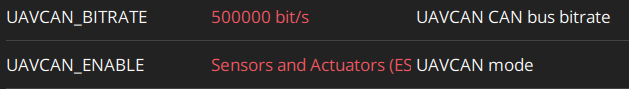
Flight Controller Configurations for DroneCAN in QGroundControl
Arming and Disarming with ArduCopter for Timer Based Protocols on PWM and DroneCAN
This example covers one way to set up a Vertiq module and a flight controller programmed with ArduCopter to properly arm and disarm in sync with each other using arming and disarming throttle regions. The same setup works for both PWM and DroneCAN control.
This example assumes that the flight controller is already properly configured to send out Standard PWM or DroneCAN commands, only the arming specific setup steps are covered here.
Module Setup
First, configure the arming throttle region on the Vertiq module. To do this, ensure that Arm on Throttle is set to Arm on Throttle in the Control Center, to turn on the arming throttle region. Then, set the Arm Throttle Upper Limit to 0.07 and the Arm Throttle Lower Limit to 0.03. This means that any throttle command between 3% and 7% will be treated as an arming throttle. The flight controller’s arming throttle will be configured to be at 5%, right in the middle of this range. So this region choice provides some tolerance for the arming throttles.
Set the Consecutive Arming Throttles to Arm to 10, so the module is less likely to arm unintentionally if there is any electrical noise. These configurations are all shown below in the IQ Control Center.
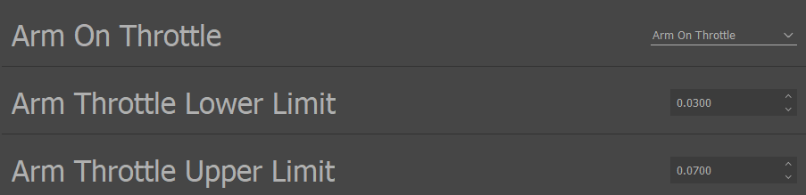
Arming Throttle Region Setup in IQ Control Center

Consecutive Arming Throttles Setup in IQ Control Center
Next, set up the disarming throttle region. Disarm on Throttle should be set to Disarm on Throttle, Disarm Throttle Lower Limit should be set to 0.00, and Disarm Throttle Upper Limit should be set to 0.03. Any throttle command from 0% to 3% will be considered a disarming throttle. The flight controller will be configured to not send a throttle command under 5% when armed, so these settings should make the module only disarm when the flight controller does. These configurations are shown below in the IQ Control Center.

Disarm on Throttle in IQ Control Center
Disarming Throttle Region Boundaries in IQ Control Center
Finally, the disarm behavior should be configured appropriately as well. For this example, set the Disarm Behavior to Coast and the Disarm Song Playback Option to Play Once. Other choices would also work, these are just simple settings to begin with. These configurations are shown below in the IQ Control Center.
Disarm Behavior in IQ Control Center
Disarm Song Playback Option in IQ Control Center
Power off the Vertiq module and move onto configuring the flight controller.
Flight Controller Setup
This example assumes that the flight controller is already set up to properly send PWM or DroneCAN commands, and only covers arming specific setup. For a more complete walkthrough on how to set up an ArduCopter flight controller, see the tutorial on flight controller setup.
The only additional parameter that must be set on the flight controller for proper arming integration is MOT_SPIN_ARM. This parameter determines the minimum throttle sent by the flight controller when it is armed. Set MOT_SPIN_ARM to 0.05, so that the flight controller sends a 5% throttle command when armed, which is in the middle of the arming throttle region that was set up on the module. When disarmed, the module will send a 0% throttle command, which falls in the disarming throttle region of the module. This setting applies to both Standard PWM and DroneCAN. The image below shows the MOT_SPIN_ARM parameter in QGroundControl.

MOT_SPIN_ARM Parameter in QGroundControl
Legacy Arming Support
Please note that if your module does not yet support the redundant throttle feature, it will be subject to arming source lockout and other throttle source requirements. See your module’s family page to see if redundant throttle is supported on your module’s firmware. The limitations of non-redundant throttle based arming are discussed below.
Armed Throttle Source Lockout
When armed, the module will always choose one throttle source as its armed throttle source, and reject incoming throttle commands from all other throttle sources. For an explanation on what is a throttle source, see the Throttle Sources section. These rejected throttle commands will not affect how the module is spinning and will not trigger disarming transitions. For example, if DroneCAN was the armed throttle source, throttle commands received over DroneCAN would be treated normally, and throttle commands received over timer based PWM would be rejected.
How the module determines the armed throttle source depends on how the arming transition is triggered. See the individual sections on types of arming transitions in Armed State Transitions for more details.
Consecutive Arming and Disarming Throttles
Consecutive arming or disarming throttles must be from the same throttle source. A change in the source of arming throttles will cause the count to reset. For example, if 5 arming throttles are sent over DroneCAN, and then 1 arming throttle is received over hobby PWM, the count of consecutive arming throttles will be 1. The change of source for the arming throttles caused a reset of the count.
To summarize, the module must receive a user-configurable number of consecutive throttle commands all in the arming or disarming throttle region and all from the same source to trigger an arming state transition.
Manual Arming Throttle Source
When the module is armed, it must have a specific throttle source set as its armed throttle source, so it knows to reject throttles from other sources for spinning and disarming. See the Armed Throttle Source Lockout section for more information on this.
When the module arms using throttle regions as described in Throttle Regions, then the armed throttle source is determined by the throttle source that sent the needed consecutive throttle commands. When a user manually arms the module using commands or the module is set to always armed, it is not clear what source they intend the module to take throttle commands from.
The Manual Arming Throttle Source is a parameter that allows users to configure what throttle source they want the module to use as its armed throttle source when arming manually. This parameter can be set in IQ Control Center under the Advanced tab, as shown below.

Manual Arming Throttle Source Parameter in IQ Control Center
When the module is armed manually or when using always armed, it will use the Manual Arming Throttle Source as its armed throttle source. That means that it will only listen to throttle commands from the specified source for spinning and disarming when it is armed manually. For example, if you had the Manual Arming Throttle Source set to DroneCAN and manually armed the module, then any throttle commands from DroneCAN would be accepted, but any sent over Standard PWM would be rejected. It is essential to set the Manual Arming Throttle Source before attempting to arm manually.