High Power PWM Output Interface
Module Support
The user high power PWM output interface is supported by only the Fortiq-42 modules.
Description
Vertiq’s high power PWM output interface provides access to a PWM output driver with read/write accessibility to the frequency, duty cycle, and mode. At the hardware level, this driver is an open-drain MOSFET without an internal pull up resistor. The mode parameter determines which portion of the PWM cycle the duty cycle represents, high or low, and is dependent on your application’s hardware setup.
Frequency is described in Hz. Frequency has a minimum of 1Hz and is limited to 5000Hz.
As mentioned above, mode’s impact is hardware dependent. If, for example, you use the hardware setup described in Initial High Power PWM Output Setup and Testing with IQ Control Center , pulling up to Vpower , mode will function as follows:
With mode set to 0, setting a duty_cycle of 75 has the following output:

With mode set to 1, setting a duty_cycle of 75 has the following output:

Without pulling up to Vpower , mode will have the opposite impact on the duty cycle.
Usage
Initial High Power PWM Output Setup and Testing with IQ Control Center
The IQ Control Center provides the easiest way to interact with your module’s PWM peripheral. To do so:
Open IQ Control Center. If you have not installed the program, please follow the instructions in Getting Started with Speed Motors Using IQ Control Center.
Connect your module to IQ Control Center
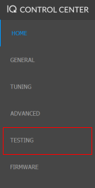
Select the Testing Tab on the left side:
Scroll down in the Testing Tab until you find PWM Output Duty Cycle
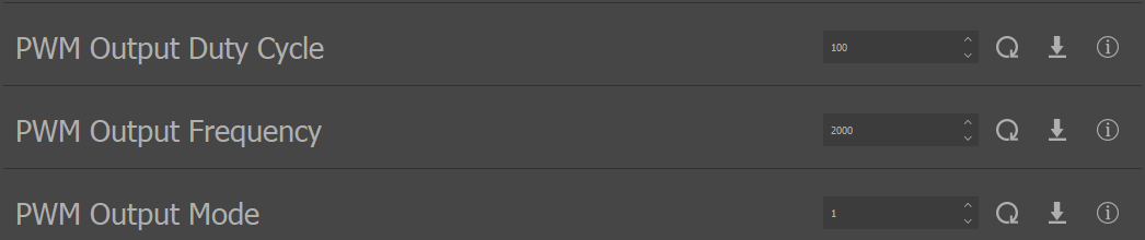
To change a value, either type in your desired value, or use the arrows
To save the value to the module click the set arrow icon
 .
.To test your PWM output, use the following simple circuit
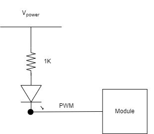
By changing the PWM duty cycle, you should see the LED change intensity.
Vertiq Python API - PWM Interface
Note
Please note that the following PWM output interface testing was performed with a Fortiq-42 module. Your exact commands may change depending on the module in use.
Vertiq’s PWM interface can also be accessed through Vertiq’s Python API. Through the API you gain read/write access to the PWM parameters duty cycle, frequency, and mode. Please note, only mode and frequency are savable values. To use the API, please use the following steps:
If you have never used Vertiq’s Python API, you must first set up your local computer to use the Python API using the instructions found at Getting Started with Python
After completing the walkthrough, you can interact with the pwm_interface client
To read a value, use the fortiq.get command. For example, to read the PWM output frequency:
print(fortiq.get("pwm_interface", "pwm_frequency"))
To write a value, use the fortiq.set command. For example, to set a duty cycle of 45:
fortiq.set("pwm_interface", "duty_cycle", 45)
To save a value, use the fortiq.save command. For example, to save the PWM mode:
fortiq.save("pwm_interface", "pwm_mode")