Vertiq 81-XX Family
Size |
Kv |
Default Firmware |
Available Firmware |
|---|---|---|---|
81-08 |
85 |
Speed |
Speed, Servo |
81-08 |
150 |
Speed |
Speed, Servo |
81-08 |
240 |
Speed |
Speed, Servo |
Size |
Kv |
Default Firmware |
Available Firmware |
|---|---|---|---|
81-08 |
85 |
Speed |
Speed, Servo |
81-08 |
140 |
Speed |
Speed |
81-08 |
240 |
Speed |
Speed |
81-17 |
110 |
Speed |
Speed |
81-XX Generation 1 (G1) Hardware Setup Walkthrough
What’s in the Box
Every Vertiq 81-XX G1 module is packaged with the following
Vertiq 81-XX G1 in the Box
1 Vertiq G1 81-XX module
Pinout and Connectors
More information about your module’s electrical characteristics and connections can be found in the datasheet provided below.
Warning
- To ensure the safe and reliable operation of this product, all electrical connections must be properly strain-relieved during aircraft assembly. Failure to do so may result in wire fatigue, breakage, or intermittent electrical contact, which can lead to system malfunction or in-flight failure.
Strain Relief Required: All wire harnesses connected to the motor, ESC, or any other component must be secured using appropriate strain relief methods to prevent mechanical stress on solder joints, connectors, and wire insulation.
Bend Radius Consideration: When routing wires, maintain a minimum bend radius appropriate for the wire gauge and insulation type to avoid excessive stress and long-term degradation.
Dynamic Loading: Consider vibration, movement, and thermal cycling in your design to ensure wires are not allowed to flex or tug under operational conditions.
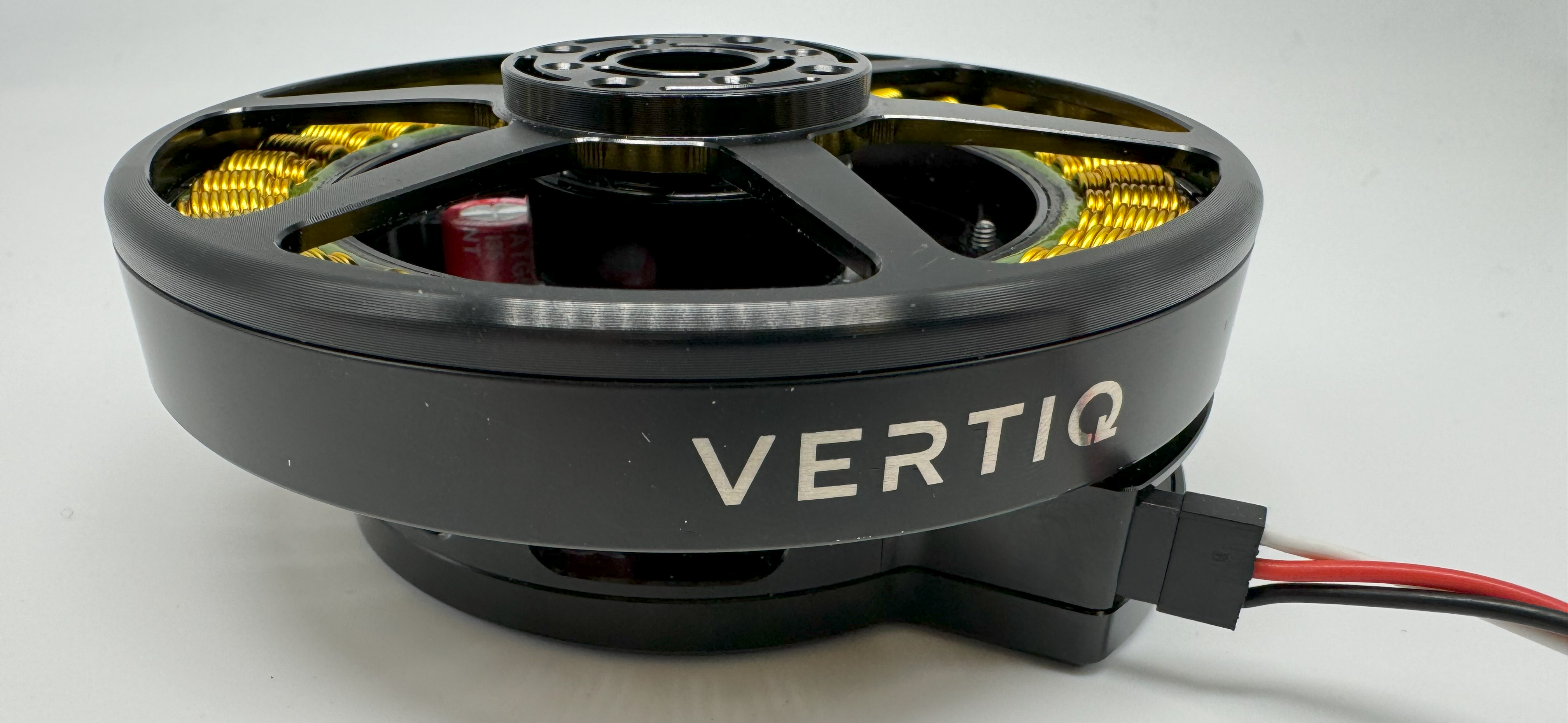
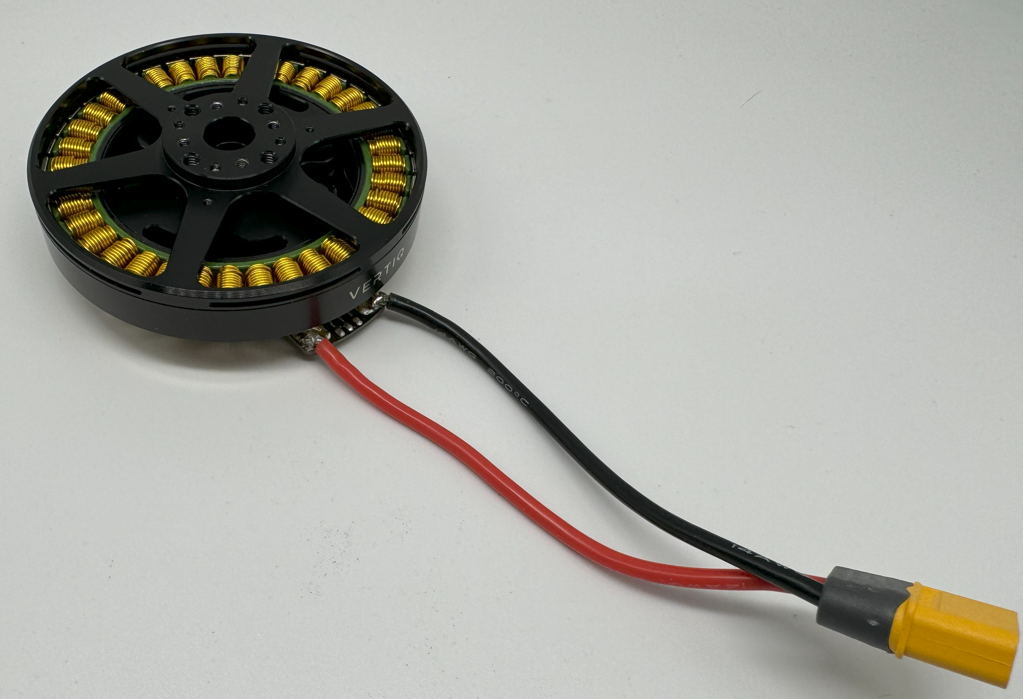
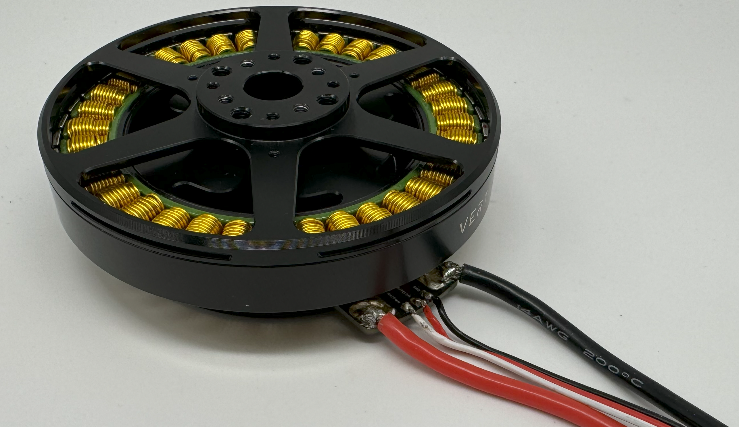
Below is an 81-XX G1 with all connections
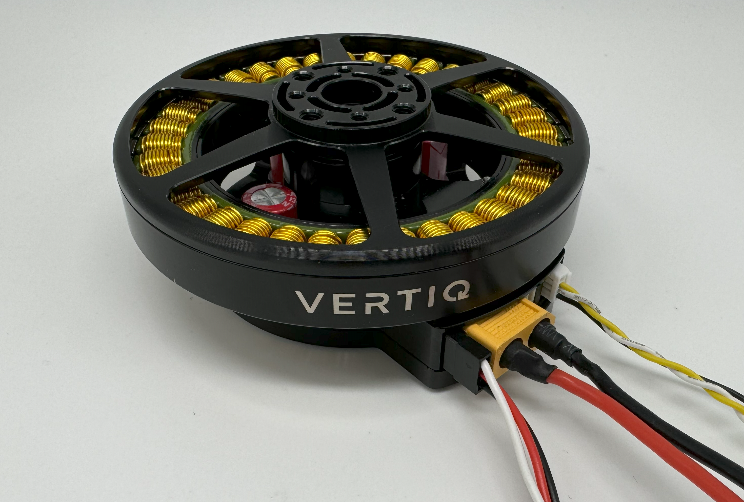
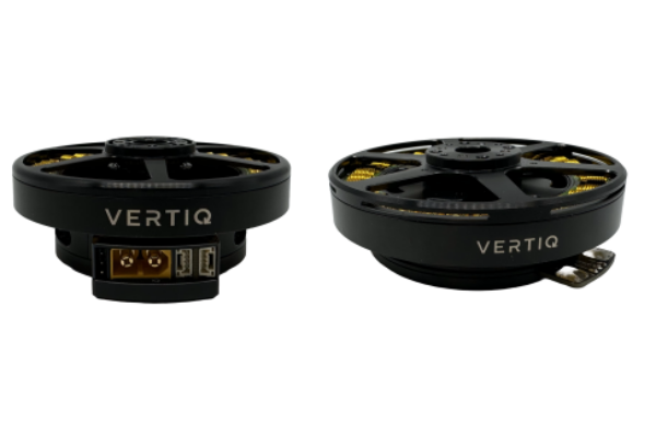
Final Vertiq 81-XX G1 Family
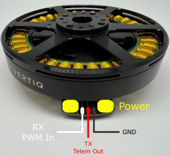
Power
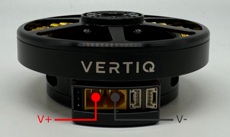
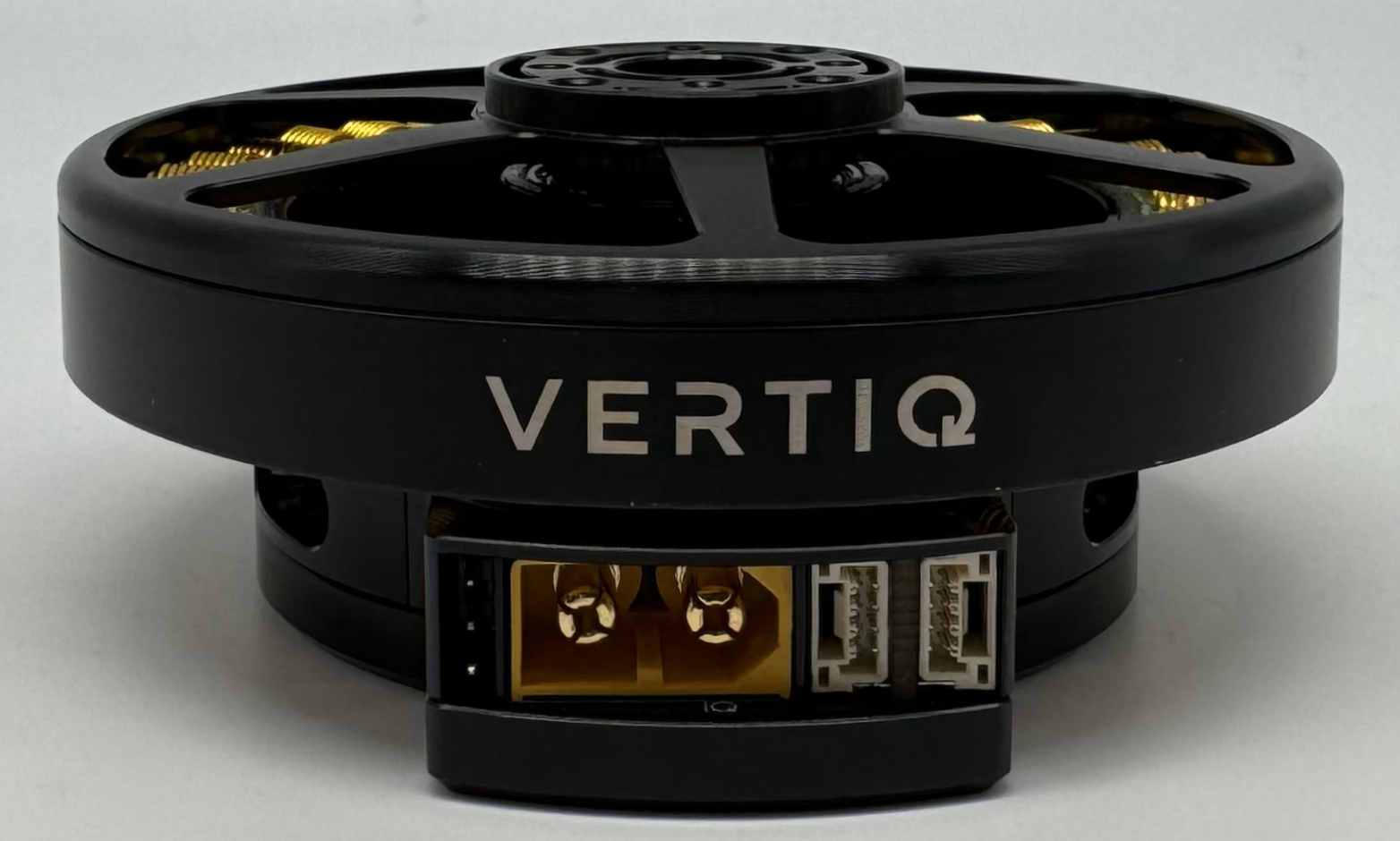
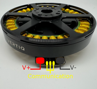
Vertiq 81-XX G1 Power Connections
All Vertiq 81-XX G1 modules feature an embedded XT-60 male connector for power. To power your module, simply fit your power supply with an XT-60 female connector ensuring that your power source’s V+ goes to the module’s V+ and V- to V-.
All Vertiq 81-XX G1 modules are rated for a maximum 12S (50.4V) across the power terminals V+ and V-. It is recommended that the supplied voltage remain between 12 and 48V at all times.
Please ensure that you select power wiring suitable for your application. Failure to do so can result in dangers like short circuits and fire.
Communication
Required IQUART or Timer Based Configuration
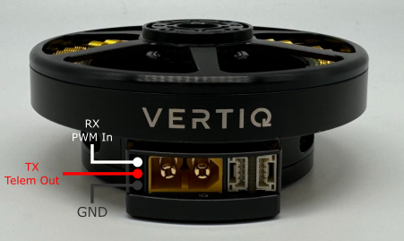
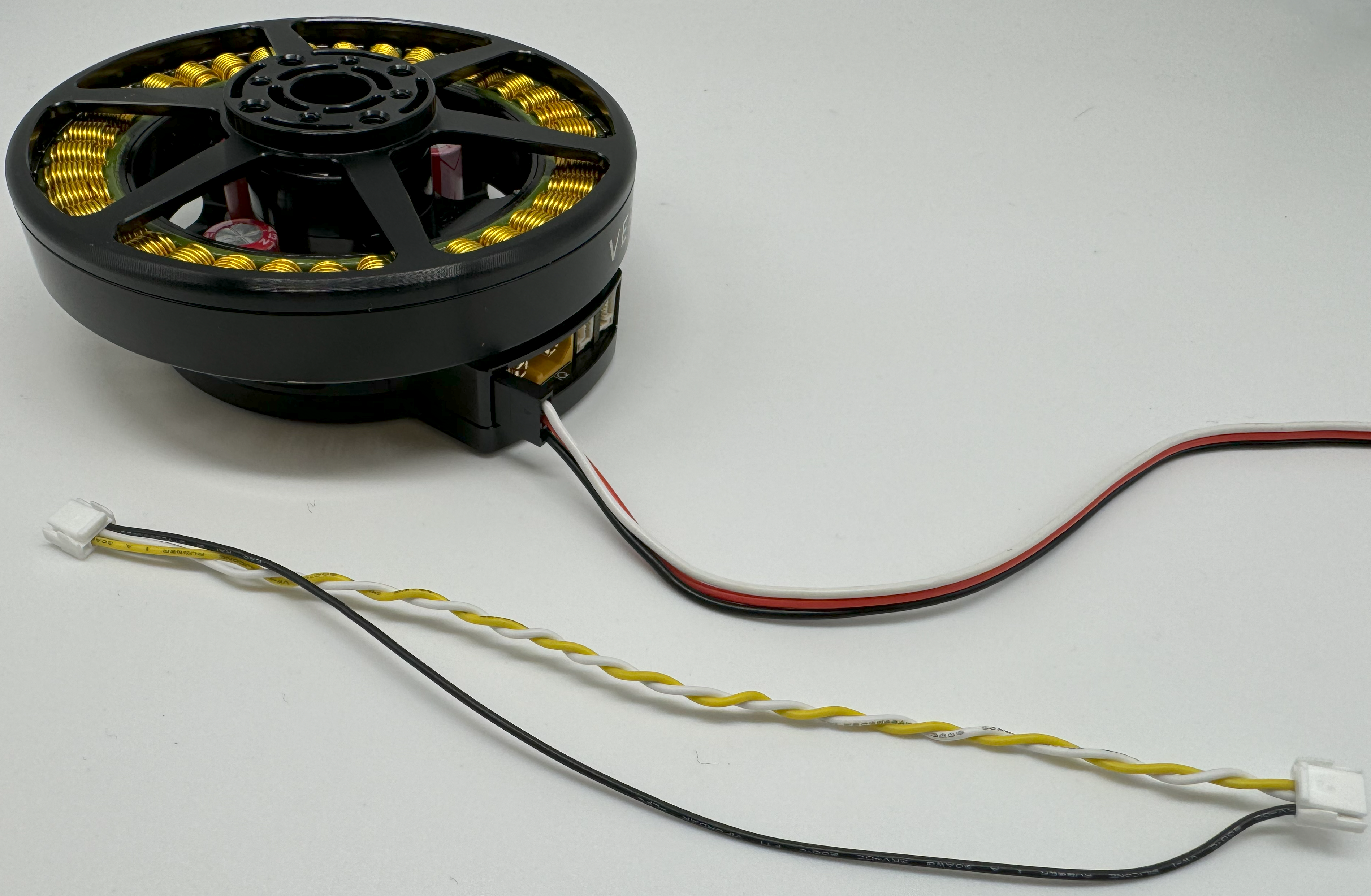
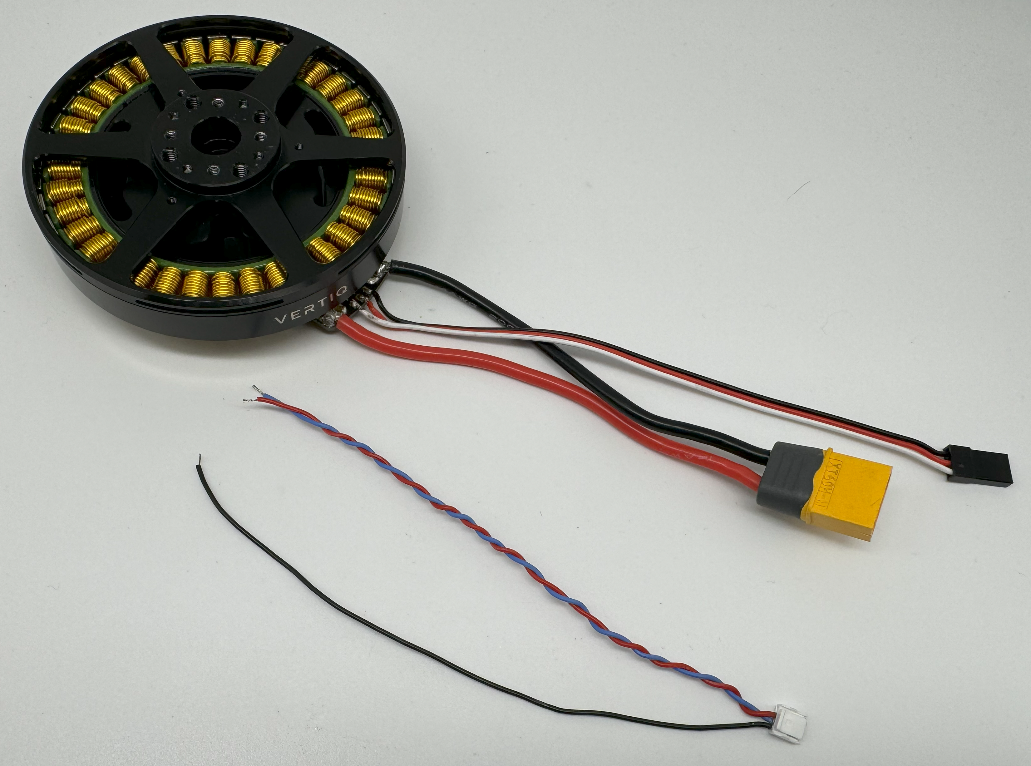
Vertiq 81-XX G1 Family Serial Connections
In order to use either IQUART or any Timer Based Protocols you will have to connect communication wiring to your module. In any scenario, please ensure that the TX line of your module is connected to your controller’s RX line, and the RX line of your module is connected to your controller’s TX line.
Please note that in order to configure your module through the IQ Control Center, to communicate with your module with any of our APIs, or to complete any firmware updates you must connect communication wires as each of these uses IQUART communication.
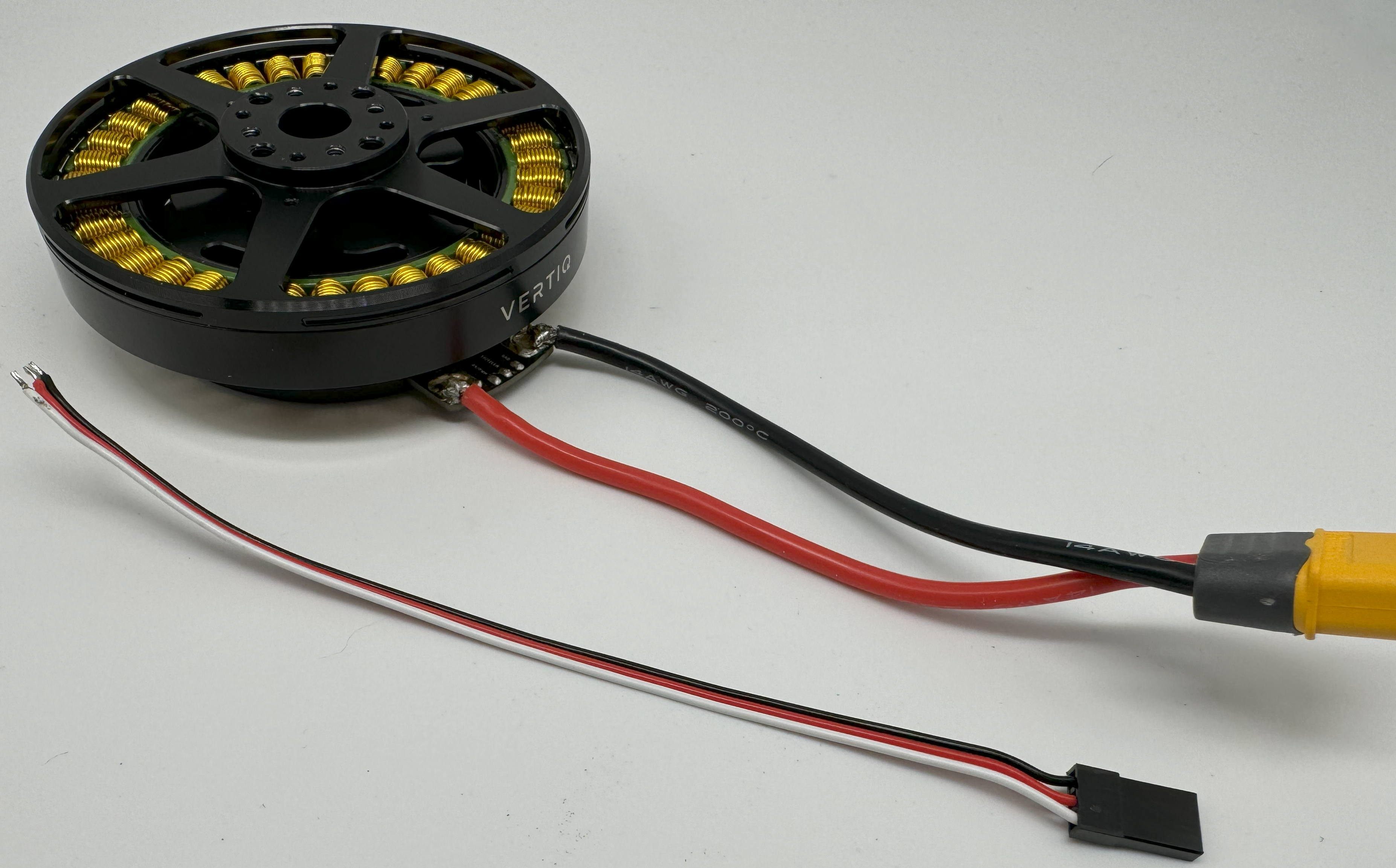
In this example, we are using a premade Servo Jr cable. No soldering is necessary, simply plug in the connector with the black cable facing down.
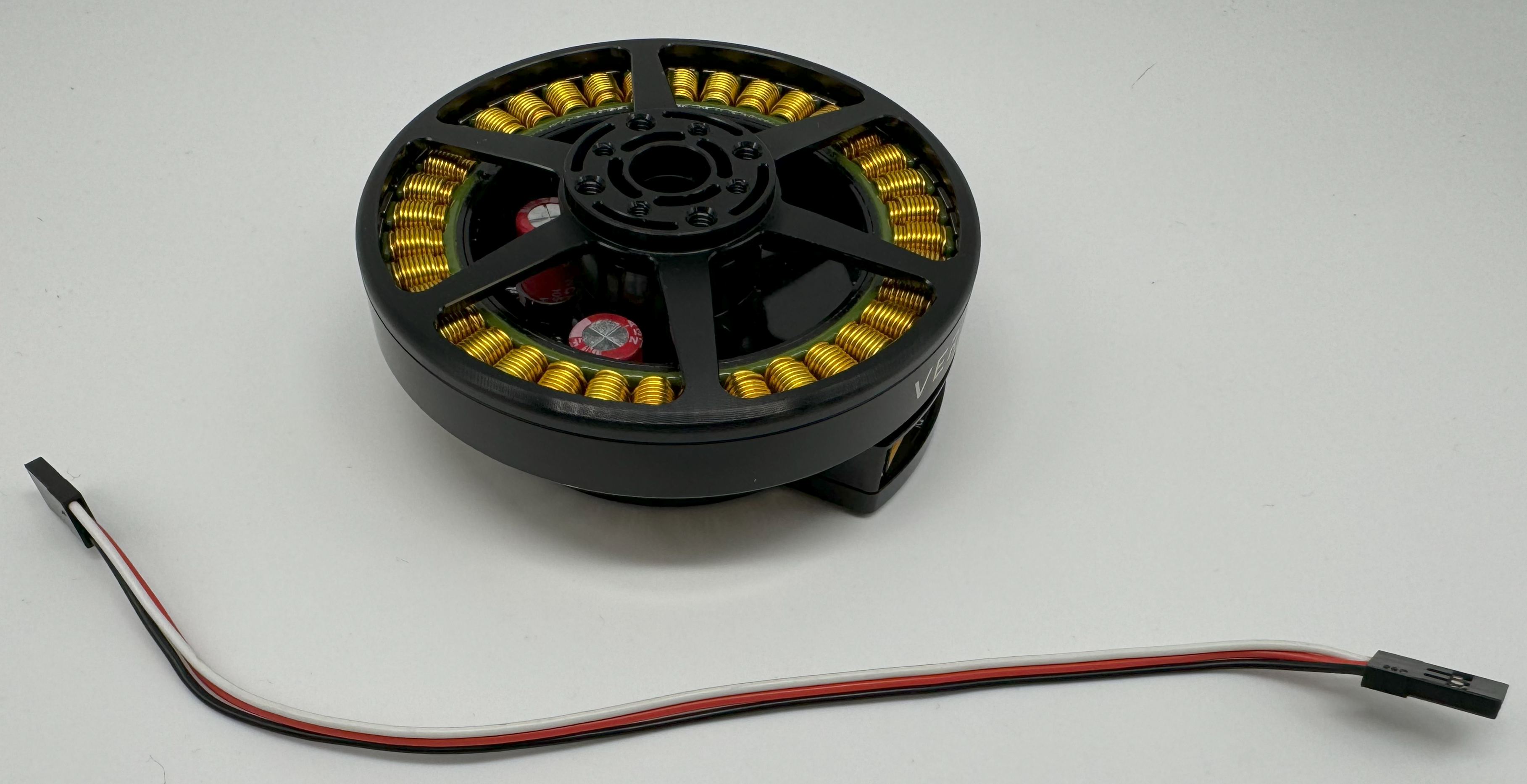
Vertiq 81-XX G1 with Serial Cable
Vertiq 81-XX G1 with Serial Cable Connected
If you intend to control your module with the DroneCAN (previously UAVCAN) protocol, please continue on to DroneCAN Configuration.
Optional DroneCAN Configuration
You will find the CANBUS (CAN) connections on the right side of the module when facing the module’s connectors.
The board supports up to two CAN connections, both of which are connected to the same peripheral allowing for a true bus connection through the motor. This configuration does not allow dual CAN redundancy.
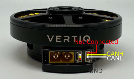
Vertiq 81-XX G1 CAN Connections
81-XX G1 modules use the DroneCAN Micro Connector based on a JST-GH 4-Pin connector with the male end embedded into the module. The modules do not support the 5V bus connection, but do connect the ground connection to common ground. More information about DroneCAN connections can be found here.
To connect with the module’s DroneCAN node, simply make a cable with a JST-GH 4-Pin connector with the correct wiring, and plug it in.
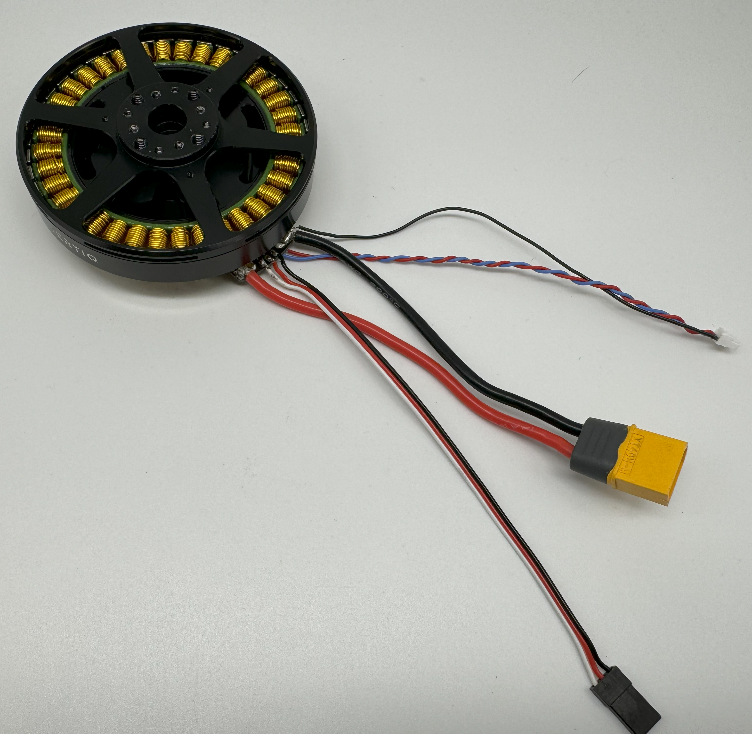
Vertiq 81-XX G1 with CAN Cable
Vertiq 81-XX G1 with CAN Cable Connected
Next Steps
Now that you have successfully wired your module for use, feel free to complete the Getting Started Guide for your module and its firmware style.
Note
While the images below show an 81-08 size module, these setup instructions are also valid for an 81-17 size module.
81-XX Generation 2 (G2) Hardware Setup Walkthrough
What’s in the Box
Every Vertiq 81-XX G2 module is packaged with the following
Vertiq 81-XX G2 in the Box
1 Vertiq G2 81-XX module
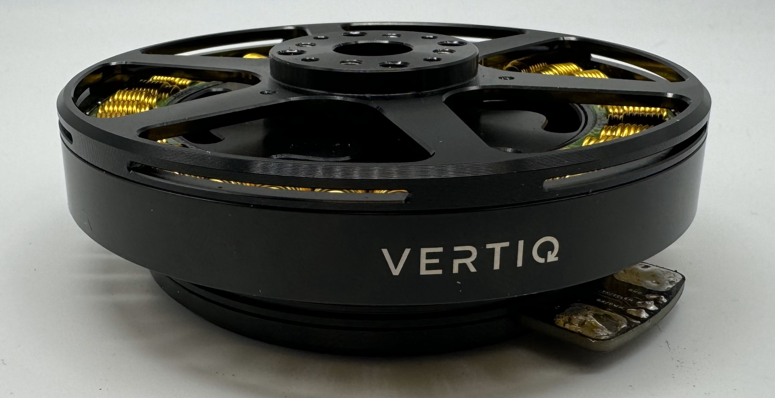
Pinout and Connectors
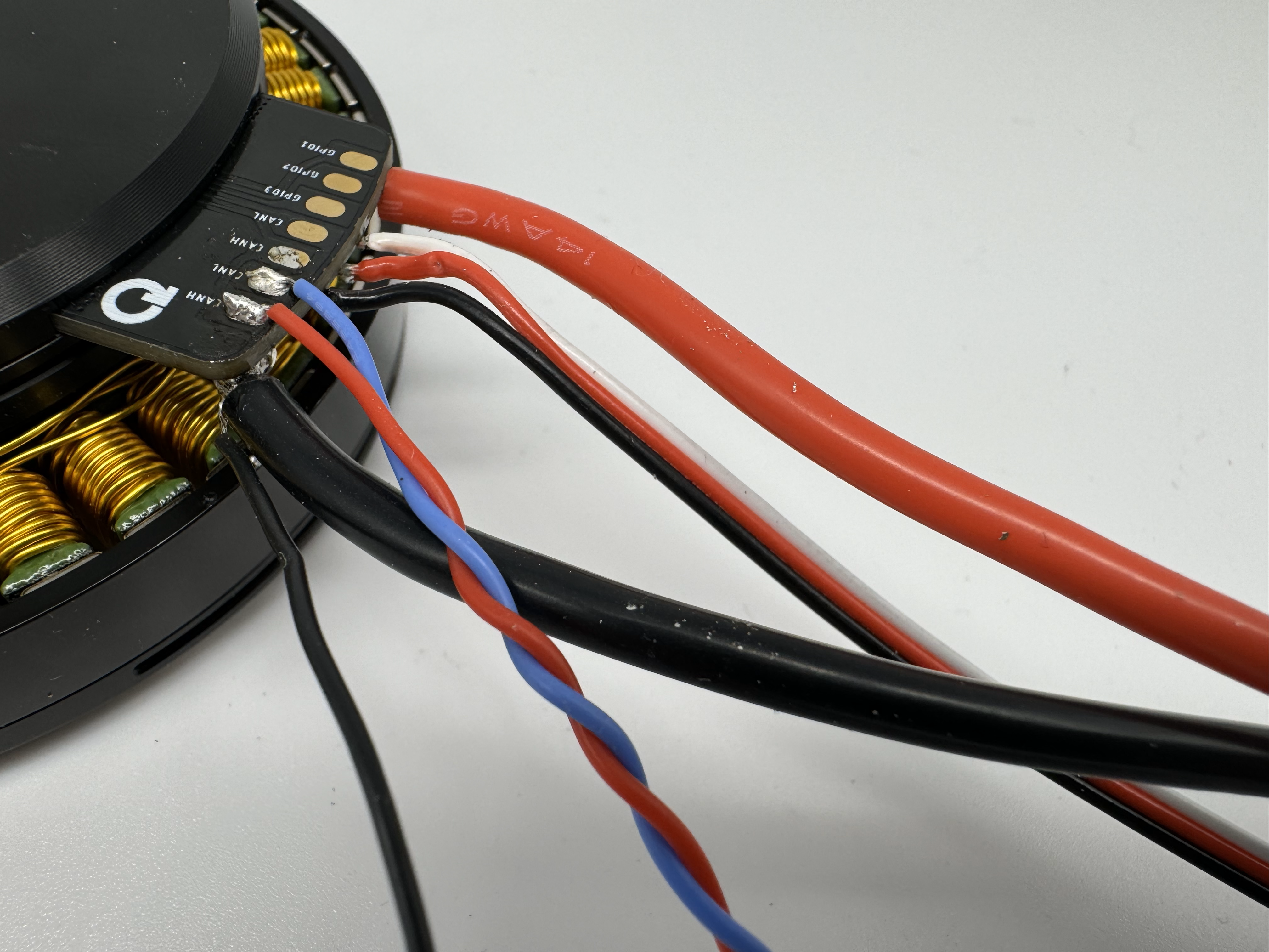
The stock Vertiq 81-XX G2 family does not support any connectors, and only accepts direct soldering to the exposed pads.
More information about your module’s electrical characteristics and connections can be found in the datasheet provided below.
Note
It is highly recommended for your and your module’s safety that you shroud all connections with the supplied heat shrink. We recommend using a ¾” diameter heat shrink with a 3:1 shrink ratio.
Warning
- To ensure the safe and reliable operation of this product, all electrical connections must be properly strain-relieved during aircraft assembly. Failure to do so may result in wire fatigue, breakage, or intermittent electrical contact, which can lead to system malfunction or in-flight failure.
Strain Relief Required: All wire harnesses connected to the motor, ESC, or any other component must be secured using appropriate strain relief methods to prevent mechanical stress on solder joints, connectors, and wire insulation.
Bend Radius Consideration: When routing wires, maintain a minimum bend radius appropriate for the wire gauge and insulation type to avoid excessive stress and long-term degradation.
Dynamic Loading: Consider vibration, movement, and thermal cycling in your design to ensure wires are not allowed to flex or tug under operational conditions.
Below is an 81-XX G2 with all connections and heat shrink
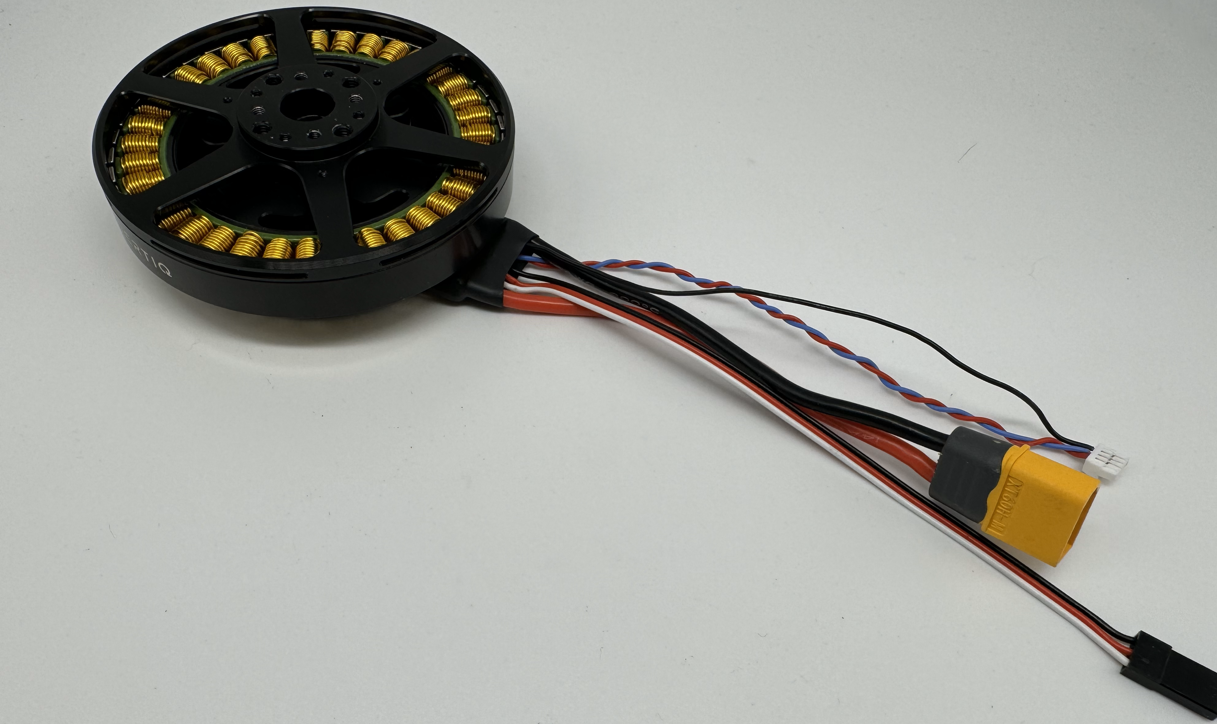
Final Vertiq 81-XX G2 Family with Heatshrink
Power
Vertiq 81-XX G2 Power Connections
All Vertiq 81-XX G2 modules are rated for a maximum 12S (50.4V) across the power terminals V+ and V-. It is recommended that the supplied voltage remain between 12 and 48V at all times.
Please ensure that you select power wiring suitable for your application. Failure to do so can result in dangers like short circuits and fire. In this example, we will be using a pre-tinned XT-60 male connector. Simply solder the connector’s positive terminal to V+ and the negative terminal to V-.
Vertiq 81-XX G2 Power Connected
Communication
Required IQUART or Timer Based Configuration
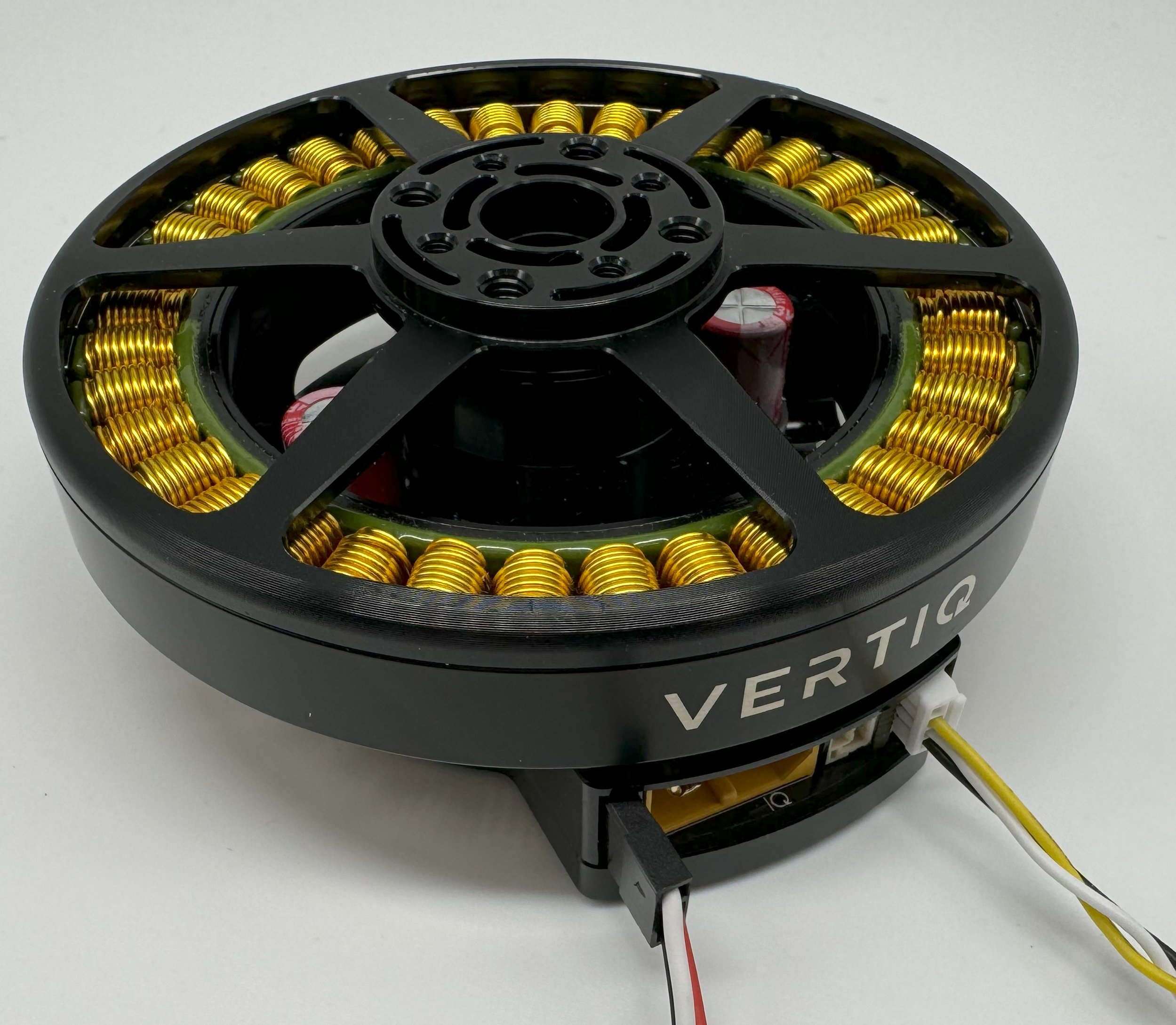
Vertiq 81-XX G2 Serial Connections
In order to use either IQUART or any Timer Based Protocols you will have to connect communication wiring to your module. In any scenario, please ensure that the TX line of your module is connected to your controller’s RX line, and the RX line of your module is connected to your controller’s TX line.
Please note that in order to configure your module through the IQ Control Center, to communicate with your module with any of our APIs, or to complete any firmware updates you must connect communication wires as each of these uses IQUART communication.
In this example, we are using a premade Servo Jr cable
Vertiq 81-XX G2 Serial Cables
Vertiq 81-XX G2 Serial Connections
If you intend to control your module with the DroneCAN (previously UAVCAN) protocol, please continue on to DroneCAN Configuration.
Optional DroneCAN Configuration
You will find the CANBUS (CAN) connections on the underside of the module
The board supports up to two CAN connections, both of which are connected to the same peripheral allowing for a true bus connection through the motor. This configuration does not allow dual CAN redundancy.
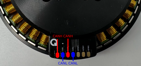
Vertiq 81-XX G2 CAN Connections
In this example, we will be using a DroneCAN Micro Connector based on a JST-GH 4-Pin connector soldered to one CANH CANL pair. We will not connect a 5V bus connection, but will solder the ground connection to common ground on the module’s top side. More information about DroneCAN connections can be found here.
Vertiq 81-XX G2 CAN Cables
Vertiq 81-XX G2 CAN Cables Connected
Vertiq 81-XX G2 CAN Cables Connected
Next Steps
Now that you have successfully wired your module for use, feel free to complete the Getting Started Guide for your module and its firmware style.
Common Hardware Setup
Attaching a Propeller for Flight
Note
It is highly recommended to apply a threadlocker, like Loctite 243, to each of the screws when attaching to the module.
The exact setup will differ for each propeller. Please follow the instructions supplied with your specific propeller.
The 81-XX family has options for mounting with both M4 and M3 bolts in the following pattern
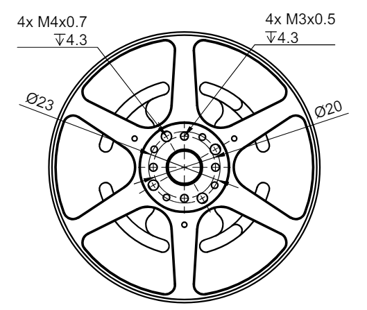
Vertiq 81-XX Propeller Mounting Pattern
Warning
Please remove the propeller before performing any startup procedures and Getting Started manuals. Failure to do so can be dangerous. Only attach propellers when your modules will be in flight, and all surroundings have been cleared.
Additional Mechanical/Electrical Information
Number of pole pairs - 21
For more information about the Vertiq 81-XX family’s mechanical and electrical characteristics please visit the correct datasheet for your module using the links below
Changing or Updating Firmware
Please follow the instructions found in Updating Firmware with the Control Center
More Information
Once you have completed the proper “Getting Started Guide,” you can begin to dive deeper into your module’s capabilities. To learn about all of the features supported by your module, please review our supported features table.
Speed Module
Supported Features
You can find a listing of all supported features by each firmware style in Supported Features.
Redundant Throttle Support - v0.1.0 and above
Supported IQUART Clients
Type ID 104 | Throttle Source Manager - v0.1.0 and later
Servo Module
Supported Features
You can find a listing of all supported features by each firmware style in Supported Features.
Supported IQUART Clients
Type ID 80 | UAVCAN Node - v0.1.1 and later
Type ID 88 | IQUART Flight Controller Interface - v0.1.1 and later
Type ID 100 | RGB LED - v0.1.1 and later
Type ID 101 | White LED - v0.1.1 and later