G2 Add-On Assembly Instructions
Vertiq’s second generation (G2) motors and ESCs are designed to be modular, accepting a wide range of mechanical and electrical attachments, or “add-ons,” to improve motor performance or introduce new capabilities. “Kits” come with both a module and separate add-ons. The assembly instructions for these add-ons are below. Please see the bottom of the page for visual aids as well.
Note
Please see the visual aids at the bottom of this page for more information about the add-ons.
Default Kit
Note
Please review the “Warnings” below in the Pro Kit section, as they may be applicable to your product as well.
Vertiq’s Default Modules allow customers to test and integrate their modules quickly and easily. These modules are characterized by a side-eject connector board with solder pads that can accept a wide range of power, communication, and LED wires.
Some (not all) Default Modules come as Kits when Vertiq provides a propeller adapter and accompanying screws. For electrical interface instructions, please visit the Hardware Setup Walkthrough on your product’s page in ReadTheDocs. For Default Kits, please follow standard propeller adapter instructions provided by your propeller supplier.
Performance Kit
Note
Please review the “Warnings” below in the Pro Kit section, as they may be applicable to your product as well.
Vertiq’s Performance Kits showcase the module’s peak performance. These are Default Modules that come with a separate rotor cover. Below is a brief description of the rotor cover and assembly instructions. For electrical interface instructions, please visit the Hardware Setup Walkthrough on your product’s page in ReadTheDocs.
Description: The rotor cover is fastened to the top of the motor to increase airflow through the rotor and protect the motor from foreign object debris. The parts that make up the Performance Kit’s Rotor Cover include:
RCM (Qty. 1) - plastic blower fan made of PA 12 glass-filled nylon
ADP (Qty. 1) - machined aluminum spacer for propeller adapter
SCR (Qty. 3) - M2 screws to fasten the RCM to the motor’s rotor
Assembly Instructions:
| Step | Description | Visual |
|---|---|---|
| 1 | Place the RCM on the motor’s rotor, aligning the 3 screw holes in the RCM with the 3 screw holes in the spokes of the rotor. |  |
| 2 | Screw the SCRs into the RCM to fasten it to the rotor. We suggest using an appropriate threadlocker, such as Loctite 243, to prevent screws from backing out during operation. |  |
| 3 | Place the ADP in the center of the RCM, aligning its holes with those on the rotor. |  |
4 | The customer will need to acquire screws of the appropriate length to go through their propeller, the ADP, and into the rotor. We suggest using an appropriate threadlocker, such as Loctite 243, to prevent screws from backing out during operation. |
Pro Kit
Vertiq’s Pro Kits are designed to give customers the ability to optimize their propulsion system for their vehicle. Different combinations of these add-ons will result in higher performance, increased IP rating, and/or new functionality. Vertiq’s Pro Module has an IP-sealable stator cover and downward-eject wires already attached to the module. A number of add-ons, including rotor covers, coil covers, stator sealer, and LEDs, come separately and make up the Pro Kit. Below is a brief description of the add-ons and assembly instructions.
Rotor Cover
Description: The rotor cover is fastened to the top of the motor to increase airflow through the rotor and protect the motor from foreign object debris. The parts that make up the Pro Kit’s Rotor Cover include:
RCM (Qty. 1) - plastic blower fan made of PA 12 glass-filled nylon
ADP (Qty. 1) - machined aluminum spacer for propeller adapter
SCR (Qty. 3) - M2 screws to fasten the RCM to the motor’s rotor
SCN (Qty. 1) - mesh screen to protect from >1mm debris
Warning
To ensure the safe and reliable operation of this product, a centering pin must be properly utilized when mounting propellers during propulsion assembly, and you must ensure all propellers are properly balanced. Failure to adhere to these practices may result in significant mechanical vibrations, which can severely impact overall vehicle performance and drastically reduce the operational lifetime of critical vehicle components, including the motor and ESC.
Assembly Instructions:
| Step | Description | Visual |
|---|---|---|
| 1 | Place the SCN over the top of the motor’s rotor, aligning the 3 screw holes in the mesh with the 3 screw holes in the spokes of the rotor. |  |
| 2 | Place the RCM directly on top of the mesh, aligning the 3 screw holes in the RCM with the 3 screw holes in the spokes of the motors. Make sure the mesh, which is sandwiched between the motor and RCM maintains its alignment. | |
| 3 | Screw the SCRs into the RCM and SCN to fasten them to the rotor. We suggest using an appropriate threadlocker, such as Loctite 243, to prevent screws from backing out during operation. | |
| 4 | Place the ADP in the center of the RCM, aligning its holes with those on the rotor. | |
| 5 | The customer will need screws of the appropriate length to go through their propeller, the ADP, and into the rotor. We suggest using an appropriate threadlocker, such as Loctite 243, to prevent screws from backing out during operation. |
Coil Cover
Description: The coil cover is fastened around the motor and underneath the coils. It is designed to protect the underside of the coils from foreign object debris. The parts that make up the Pro Kit’s Coil Cover include:
Note
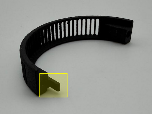
If your coil cover has the tab highlighted in the image below, please refer to the instructions here.
CCM (Qty. 2) - plastic part made of PA 12 glass-filled nylon designed to protect from >1mm debris. Two of these parts are needed for the coil cover.
SCR (Qty. 2) - M2 screws to fasten the two CCMs together around the motor
Assembly Instructions:
| Step | Description | Visual |
|---|---|---|
| 1 | Place the two CCMs beneath the coils and around the motor, aligning them with each other to allow the screws to hold them together. Align the dots of the CCMs with the circuit board on the Default Module or where the cables are on the Pro Kit. |  |
| 2 | Screw the SCRs into the CCMs, ensuring they are securely fastened and the motor can freely rotate. |  |
Stator Cover Seal
Description: The Pro Kit comes with an IP-sealable stator cover already assembled onto the module. To seal the module to the drone arm, Vertiq provides an O-ring:
RNG (Qty. 1) - O-ring to prevent liquid ingress into the ESC compartment
Assembly Instructions:
| Step | Description | Visual |
|---|---|---|
| 1 | Ensure that the drone-arm-side interface between the module and drone arm is a flat surface. | |
| 2 | Place the RNG in the groove of the module’s stator cover and align the screw holes of the module with those of the drone arm. |  |
| 3 | The customer will need to acquire screws of the appropriate length to fasten their module into the drone arm. We suggest using an appropriate threadlocker, such as Loctite 243, to prevent screws from backing out during operation. |
Power & Communication
Description: The Pro Kit comes with downward eject power and communication wires coming off the ESC. Downward eject wires are necessary to IP-seal the ESC compartment.
Warning
- To ensure the safe and reliable operation of this product, all electrical connections must be properly strain-relieved during aircraft assembly. Failure to do so may result in wire fatigue, breakage, or intermittent electrical contact, which can lead to system malfunction or in-flight failure.
Strain Relief Required: All wire harnesses connected to the motor, ESC, or any other component must be secured using appropriate strain relief methods to prevent mechanical stress on solder joints, connectors, and wire insulation.
Bend Radius Consideration: When routing wires, maintain a minimum bend radius appropriate for the wire gauge and insulation type to avoid excessive stress and long-term degradation.
Dynamic Loading: Consider vibration, movement, and thermal cycling in your design to ensure wires are not allowed to flex or tug under operational conditions.
Assembly Instructions:
| Step | Description |
|---|---|
| 1 | Please see your module's family page to find the wire assembly instructions |
| 2 | You can find ESC Programming instructions here. |
LED
Description: The Pro Kit comes with an LED, as well as downward eject power and communication wires for the LED:
LD - LED board capable of white & RGB flashing
Assembly Instructions:
| Step | Description |
|---|---|
| 1 | Connect the LED board to the dedicated wires coming from the ESC downward eject connector board. Further instructions and visuals can be found here. |
| 2 | It is highly recommended to mount the LED heatsink areas to flat metal surfaces to help cool the boards. Please see the LED datasheet for more information on this. |
| 3 | Find LED programming instructions here: Stock LED support, RGB control, and White control. |

