Building and Flashing PX4 and ArduPilot Firmware with IQUART Flight Controller Interface
This tutorial covers how to build and configure PX4 Autopilot and ArduPilot for use with Vertiq’s IQUART protocol. With IQUART integrated into your flight controller, you gain the ability to control and receive telemetry from all connected modules through a single serial port. If you are using PX4, you also gain the ability to configure your modules directly through the flight controller. Please note that in order to control your module with the IQUART Flight Controller Interface (IFCI) through PX4 or ArduPilot, your module must support IFCI. The features supported by your module and firmware style can be found on your module’s family page.
Note
If you intend on using DroneCAN and a IFCI as redundant sources, please first read Redundant Throttle and Arming in order to fully understand the arming interactions that may occur between the protocols.
Building and Flashing PX4 Flight Controller Firmware
Setting Up the PX4 Toolchain
In order to build PX4, you must install the PX4 toolchain. We recommend that you follow PX4’s guides in order to install the toolchain for your specific device.
Setting Up PX4 for IQUART and Building
Once the toolchain is set up, you must change the settings for your board to turn on Vertiq IQUART integrations. To do this, enter your PX4 directory and use the command below, but replace <your-flight-control-board> with your flight control board’s name.
make <your-flight-control-board> boardconfig
For this example, we are building for the px4_fmu-v6c so we run the command below.
make px4_fmu-v6c boardconfig
This should bring up the boardconfig window in the terminal. The ‘Model’ section should have your board name. In the image below we are using an fmu-v6c.

Main Board Config Page
Navigate to the drivers subsection with the arrow keys and press Enter to enter it.

Selecting the Drivers Section
Navigate to the actuators submenu with the arrow keys and press Enter to enter it.

Selecting the Actuators Section
Navigate to the vertiq_io subsection and press Space to select it. An asterisk should appear in the box. Once the asterisk is in the box, press Enter to enter the vertiq_io submenu.

Selecting the vertiq_io Section
Inside the vertiq_io submenu one option should appear for including IFCI Configuration Parameters. Select this by pressing Space.

Include IFCI Parameters
When IFCI Configuration Parameters is selected, a second option will appear for including pulsing module configurations. If you plan on using underactuated propellers, select this as well.
When all of your desired configuration options are selected, press Q and then Y to save the configuration.

Save the Configuration
Build the firmware with the following command, replacing your-flight-control-board with the name of your flight control board. This will be the same name as used in the previous steps.
make <your-flight-control-board>
For this example, we are building for the px4_fmu-v6c so we run the command below.
make px4_fmu-v6c
Your firmware file should appear in the PX4-Autopilot/build/your-flight-control-board_default folder as your-flight-control-board_default.px4
Warning
Adding the IFCI configuration features will increase the size of the PX4 build. This could make the build larger than the flash size available on your board.

Oversized Code
If the build is too large, you will have to turn off other features to fit the binary on your flight controller. We recommend excluding other output drivers (PWM, DShot, DroneCAN, etc.) that you will not be using. Features can be turned off through boardconfig exactly as you turned on Vertiq’s features.

DShot and PWM Location
With the build settings updated, rebuild the program. When the compiled program occupies under 100% of the flash size, you will be able to fully build the PX4 application.

Trimmed Code
Flashing PX4 to Your Flight Controller
Now you will need to flash your flight controller with the newly compiled .px4 file. To do this, open QGroundControl, go to the vehicle settings menu, and enter the ‘Firmware’ menu. Once there, plug in your board, select the ‘Advanced Settings’ checkbox, and then the ‘Custom Firmware’ option. If QGroundControl does not show a pop-up, try unplugging all other USB devices that QGroundControl might confuse as a flight control board before attempting to plug your flight control board in again.

Custom Firmware Selection
Pressing ‘Ok’ will cause a file explorer to appear. Find the your-flight-control-board_default.px4 file that you built and select it. The flashing process should begin.
Enabling IFCI on Your PX4 Flight Controller
Once the flashing is complete, connect to your flight controller with QGroundControl and go to the parameters menu. In the parameters menu search for ‘vertiq’. The parameter VERTIQ_IO_CFG should appear. Select this parameter, set it to the serial port that you plan on using, save, and reboot the flight controller as instructed by QGroundControl.

Enabling Vertiq IO
After reboot, and with Vertiq IO enabled, you should now see a Vertiq IO submenu in the QGroundControl parameter settings. Adjust the VTQ_BAUD parameter to match what your modules will be using. In this tutorial, we will be using a baud rate of 921600 which is what we recommend.

Vertiq IO Submenu
Now your Vertiq modules must be configured for proper communication with the flight controller and you can find these instructions here <ifci_integration>.
Building and Flashing ArduPilot Flight Controller Firmware
In order to build ArduPilot, you must install the ArduPilot toolchain. We recommend that you follow the developer instructions.
Building ArduPilot Flight Controller Firmware
Vertiq’s ArduPilot fork includes all of the necessary updates needed to control your Vertiq modules over IFCI. To access it, first make sure you’ve set up an SSH key for GitHub, and then go to the Vertiq ArduPilot repository.
In a WSL terminal, run the following:
git clone git@github.com:iq-motion-control/vertiq_ardupilot.git --recursive
Navigate into the vertiq_ardupilot folder. In this example we’re using the MatekH743 flight controller. You will need to adjust this command to build for your specific flight controller. More information for specific hardware is available on Ardupilot’s website. You can configure your build for your flight controller with the following:
./waf configure --board MatekH743
Now build with:
./waf copter
Flashing ArduPilot to Your Flight Controller
Note
If you have not done so already, please download and install Mission Planner.
Open Mission Planner, navigate to Setup, and Install Firmware
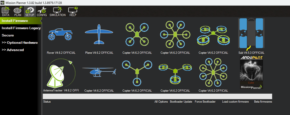
Mission Planner firmware installation
Plug in your flight controller and Mission Planner should say that it found your board. Select Load Custom Firmware, and select the .apj file you just built. Once flashed, select Connect in the top right to connect with your flight controller.