Getting Started with Vertiq’s Pulsing Firmware with IQ Control Center
To learn more about pulsing, please read the manual Pulsing Based Control Mechanisms to gain a background before continuing to get started with pulsing.
Note
This guide focuses on setting parameters on your Vertiq modules. Please refer to your hardware’s documentation (flight controller, radio, etc.) for more details on its specific configuration. For example, refer to the PX4 documentation for integrating with a PX4 flight controller.
Before completing the following getting started guide, please ensure that you have read and completed our IQ Control Center guide. It walks you through Control Center installation, module configuration, and basic testing options available to all Vertiq modules and firmware types. The following document is meant to provide additional configurations and testing options available only on Vertiq’s pulsing firmware.
Note
The following images are captured using IQ Control Center version 1.5.3 as connected to a Vertiq 23-06
Hardware Configuration for Pulsing Propellers
Vertiq’s pulsing firmware is meant to operate specifically with our UPXX propellers. Please ensure that you have completed the following guides in order to learn how to attach the propeller to your module, and to configure your module for proper flight with the propeller.
Important Parameters for Flight Controller Integration
The first set of configurations covered here are those that must be configured properly in order to control your module with a flight controller. These parameters affect how your module communicates with, and is controlled by a flight controller.
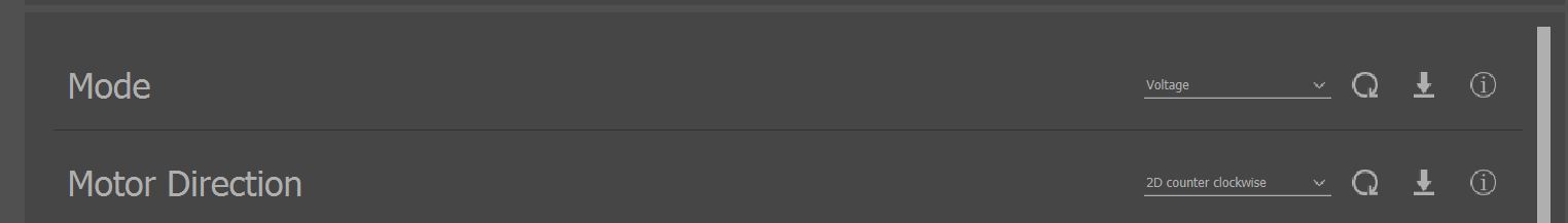
Mode: this parameter is available through the General tab, and defines whether your module accepts throttle commands as a voltage, a velocity, or a PWM. To learn more about the Mode parameter see Mode
Motor Direction: this parameter is available through the General tab, and defines the direction that your module takes to be positive, either clockwise or counter-clockwise. You can also configure either 2D or 3D configuration to allow for mapping negative throttle commands. For more on the Direction parameter and throttle mapping, see Direction
Max Velocity and Max Volts: These parameters are available through the Tuning tab, and pair directly with the Mode parameter. This means that when your mode is set to velocity, your module will only ever map a throttle command as bounded by ± Max Velocity. When your mode is set to voltage, your module will only ever map a throttle as bounded by ± Max Volts. To learn more see Maximums
IQUART Flight Controller Interface Configuration Parameters
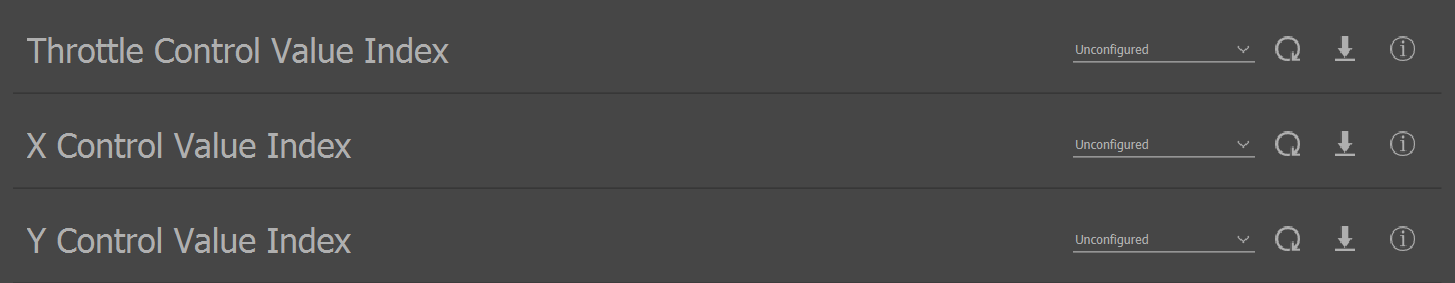
If you are controlling your pulsing module with the IQUART Flight Controller Interface (IFCI), you must configure your module’s IFCI control value indices for throttle, X, and Y commands. These parameters are available through the General tab as Throttle Control Value Index, X Control Value Index, and Y Control Value Index. More information about these control values can be found at the link above.
Timeout Configuration
Vertiq’s speed modules provide several configuration parameters regarding the module’s timeout behavior. Timeouts are triggered after a configured length of time of not receiving new commands. Timeouts and their configurations are covered in detail here.
Pulsing Torque Angle
This parameter is available through the General tab, and defines a correction factor for the difference between the torque vector and the torque induced by the force vector. Please read Underactuated Propeller Torque Angle Correction to learn more about properly setting this value for your vehicle.
Pulsing Frequency
This parameter is available through the General tab, and defines the number of pulses that happen per module rotation. This can be useful if the motor is not directly driving the propeller.
Pulsing Voltage Mode
This parameter is available through the General tab, and determines how the module decides on its maximum pulsing voltage for scaling incoming pulsing commands. In Supply Voltage mode, the supply voltage is used as the maximum pulsing voltage. In Voltage Limit mode, the maximum pulsing voltage is specified by Pulsing Voltage Limit. To learn more please read IQUART Flight Controller Interface.
Pulsing Voltage Limit
This parameter is available through the Tuning tab, and determines the maximum voltage to be applied to pulsing when Pulsing Voltage Mode is set to Voltage Limit Mode. To learn more please read IQUART Flight Controller Interface.
Pulsing Velocity Mode
This parameter is available through the General tab, and determines how the module decides on its maximum pulsing velocity for scaling incoming pulsing commands. To learn more please read IQUART Flight Controller Interface.
Pulsing Velocity Cutoff
This parameter is available through the Tuning tab, and determines the minimum required velocity to allow pulsing. To learn more please read IQUART Flight Controller Interface.
Example Module Flight Controller and Pulsing Configuration with the Control Center
Suppose that your module has the following requirements to function properly on your vehicle:
The module must spin clockwise at all times
The module must spin proportionally to a target velocity, with a maximum of 500 rad/s
The module must use IFCI index 0 for throttle, index 1 for X, and index 2 for Y commands
To configure your module to meet these requirements:
Connect with your module through IQ Control Center
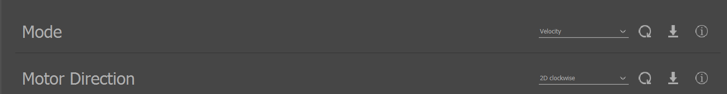
In the General tab, find the Mode parameter. Please note, the module used for this demonstration has been reset to factory defaults. If you have previously configured your module, your values may not match identically to these images
Now, we will configure the parameters required to meet our first requirement as well as the first half of our second
Set Mode to Velocity
Set Motor Direction to 2D clockwise
To meet the remainder of the second requirement, navigate to the Tuning tab, and find the Max Velocity parameter. Set it to 500 rad/s

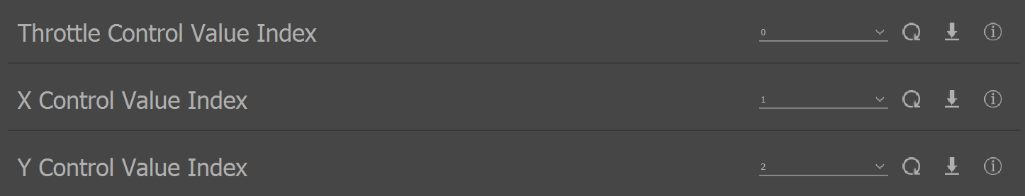
To meet the third requirement, navigate to the General tab, and find Throttle Control Value Index
Set Throttle Control Value Index to 0, X Control Value Index to 1, and Y Control Value Index to 2
To test the parameters you set with pulsing, please refer to Pulsing Based Control Mechanisms.