DroneCAN
DroneCAN (previously known as UAVCAN or UAVCANv0), is an open protocol for communication over a CAN bus. DroneCAN is supported by both PX4 and Ardupilot flight controllers. Refer to the DroneCAN documentation for more information on the protcol and the standard.
Module Support
To see if your module and firmware style supports this feature, please see our supported features table.
Standard DroneCAN Support
This section details the standard DroneCAN messages supported across all Vertiq DroneCAN modules. The structure and contents of these messages are defined by the DroneCAN specification. This section just provides details on how exactly Vertiq modules support them and some supplementary information.
Details on the DroneCAN protocol can be found on the DroneCAN specification. For a full listing of all standard messages specified by DroneCAN, see the List of Standard Data Types in the DroneCAN specification.
Broadcast Messages
These are broadcast messages that are sent to or from the motors. Broadcast messages are not intended for any specific node on the bus, data is simply transferred over the bus and is available for any node that is interested. Since they are broadcast, there is no response message sent. These messages typically make up the majority of communication on the bus during operation.
uavcan.protocol.NodeStatus (Data Type ID = 341)
Speed Firmware Support |
Servo Firmware Support |
|---|---|
Yes |
Yes (v0.1.0 and later) |
The DroneCAN protocol requires that all nodes on a DroneCAN network periodically publish their status using the Node Status message. Vertiq modules support this behavior to conform to the standard. A uavcan.protocol.NodeStatus message is published at 1 Hz during operation, reporting its health, current mode, and uptime.
Vertiq’s Node Health Indications
Vertiq modules support all four standard DroneCAN health indications. Modules enter each state given the following conditions. Please note that if any one condition is met, the module will enter that health state. For example, if your module is in timeout but it’s derate is still 1, it will enter the Error state. Also, please note that the list below is in order of health state priority. For example, if your module meets a condition for both Warning and Error, it will report its health as Error.
Critical
The module’s total derate reaches 0
Your module’s drive mode is in lockout due to power safety
Error
The module is actively in timeout
The module’s total derate is less than 1 but greater than 0
Warning
The module’s supply voltage is greater than your drive’s Volts Limit Starting Voltage. This typically indicates that the module is regenerating into a supply that cannot handle regenerated current, such as a typical benchtop power supply, and is limiting how much it regenerates to protect itself
Your microcontroller’s temperature is within 10°C of your module’s microcontroller temperature derate window
Your module’s coil temperature is within 10°C of your module’s coil temperature derate window
Healthy
When none of the conditions of Critical, Warning, or Error are met, the module is considered Healthy.
Vertiq’s Vendor Specific NodeStatus Code Breakdown
Vertiq’s vendor specific NodeStatus bits are used to indicate the state of various possible module errors. The bits are broken down as follows:
Bits [0, 7]: Indicate the value of Power Safety’s fault_now value. Please refer to the linked documentation for an additional breakdown of these bits
Bit 8: Indicates that the module’s speed derate is less than 1 but greater than 0. This means the motor is approaching an over-speed condition
Bit 9: Indicates that the module’s microcontroller temperature derate is less than 1 but greater than 0. This means that the microcontroller’s temperature is getting dangerously high
Bit 10: Indicates that the module’s coil temperature derate is less than 1 but greater than 0. This means that the coil temperature is getting dangerously high
Bit 11: Indicates that the module’s measured voltage is greater than your drive’s Volts Limit Starting Voltage. This typically indicates that the module is regenerating into a supply that cannot handle regenerated current, such as a typical benchtop power supply, and is limiting how much it regenerates to protect itself
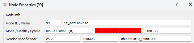
Suppose your module’s microcontroller temperature is causing a derate and at the same time, its voltage spikes beyond Volts Limit Starting Voltage, and its input current exceeds power safety’s maximum input current. We expect bits 3, 9, and 11 to go high. We also expect that the module will enter Critical health caused by the high input current. As viewed in the DroneCAN GUI tool:
Refer to the uavcan.protocol.NodeStatus section of Standard Data Types in the specification for more details.
If you are looking to view more detail about your module during flight, see uavcan.equipment.esc.Status (Data Type ID = 1034) and uavcan.equipment.esc.StatusExtended (Data Type ID = 1036).
uavcan.equipment.esc.Status (Data Type ID = 1034)
Speed Firmware Support |
Servo Firmware Support |
|---|---|
Yes |
No |
This message is published periodically and provides telemetry updates on the state of the motor and its inputs. Specifically it contains information on:
Error Count: This is either:
Firmware v0.3.0 and later: a counter of CAN bus errors (as defined at the CAN hardware level) that reports either the number of TX errors, RX errors, maximum of TX and RX errors, a logical OR of TX | RX errors, or the cumulative number of both TX and RX errors since power on. You can configure what is reported through the Error Count field either via the DroneCAN parameter esc_status_error_meaning or with
DroneCAN ESC Status Error Count Meaningin IQ Control Center’s Advanced tab.

All firmware before v0.3.0: a counter of CAN bus errors, specifically it details the number of transmit errors the motor has encountered.
Voltage: The input voltage to the motor in volts
Current: The current draw of the motor in amps
Temperature: The temperature of the motor’s coils in Kelvin or the motor’s microcontroller temperature in Kelvin depending on the value of
DroneCAN Telemetry Style. Please see uavcan.equipment.esc.StatusExtended (Data Type ID = 1036) for more information.RPM: The current speed of the motor in RPM
Power Rating Percentage: The PWM duty cycle percentage being applied to the motor, from 0% to 100%. Maximum power draw occurs at 100% duty cycle
ESC Index: The ESC index of the motor that is broadcasting this update
The frequency that this message is published at is determined by the Telemetry Frequency configuration parameter.
Refer to the uavcan.equipment.esc.Status section of Standard Data Types in the specification for more details.
uavcan.equipment.device.Temperature (Data Type ID = 1110)
Speed Firmware Support |
Servo Firmware Support |
|---|---|
Yes |
No |
Note
This message is transmitted only if DroneCAN Telemetry Style is configured to Use Old-Style Telemetry. Please see uavcan.equipment.esc.StatusExtended (Data Type ID = 1036) for more information.
This message is published periodically and provides updates on the temperature of the microcontroller used on the controller. The fields contained in this message are:
Device ID: The ESC index of the motor sending this broadcast
Temperature: The temperature of the microcontroller in Kelvin. Note that this is different from the temperature in the ESC status message, as that is the temperature of the coils.
Error Flags: Indicates if the motor is overheating with the standard ERROR_FLAG_OVERHEATING flag. See the error flag definitions on the DroneCAN documentation.
The frequency that this message is published at is determined by the Telemetry Frequency configuration parameter.
Refer to the uavcan.equipment.device.Temperature section of Standard Data Types in the specification for more details.
uavcan.equipment.esc.RawCommand (Data Type ID = 1030)
Speed Firmware Support |
Servo Firmware Support |
|---|---|
Yes |
No |
Used to control the speed and direction of the motor. This message should be sent from the flight controller to the motors. The payload consists of a list of up to 20 values, with each value interpreted as a 14 bit signed integer. Each entry in the list corresponds to a motor with the given ESC index. E.g. The first entry in the list of raw commands will be read by the motor that has been assigned ESC index 0, the second entry will be read by the motor with ESC index 1, and so on.
The values represent the speed and direction to command the motor to, normalized over a range of [-8192, 8191], with -8192 being full speed in reverse and 8191 being full speed forward.
Refer to the uavcan.equipment.esc.RawCommand section of Standard Data Types in the specification for more details
uavcan.tunnel.Broadcast (Data Type ID = 2010)
Speed Firmware Support |
Servo Firmware Support |
|---|---|
Yes |
Yes (v0.1.0 and later) |
DroneCAN’s “tunnel” messages allow users to transmit arbitrary data bytes through the DroneCAN protocol. The tunnel broadcast message contains a byte representing the protocol being tunneled, a channel ID allowing for additional routing options, and an array of up to 60 bytes of data.
Vertiq modules are configured to accept broadcast messages with a protocol value of 0x55, and check the received data buffer for valid IQUART data. As such, the DroneCAN tunnel broadcast message allows users to transmit IQUART messages via DroneCAN. Vertiq modules do not support use of the channel ID for additional routing.
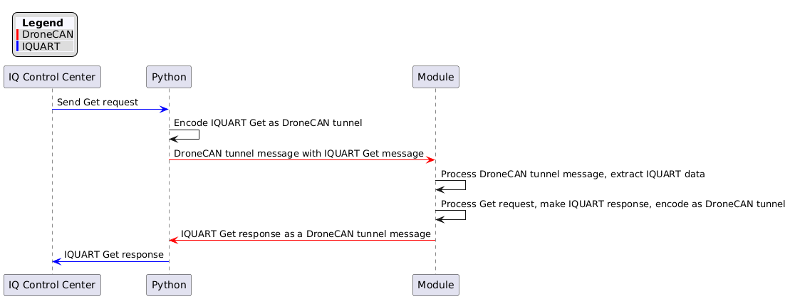
In this example, the module has no serial connection to IQ Control Center. Instead, the Control Center sends messages to a Python script which packages the IQUART bytes as a DroneCAN tunnel message, and transmits the message to the module. The module receives and decodes the IQUART message, and if necessary, forms a response as a DroneCAN tunnel message which is sent back to the Python script. Finally, the Python script pulls the IQUART response out of the module’s tunnel message, and transmits the response to the Control Center via IQUART.
A similar configuration is possible using a flight controller with a serial connection, CAN connection, and appropriate script running.
The process is summarized below.
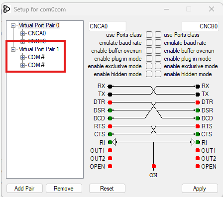
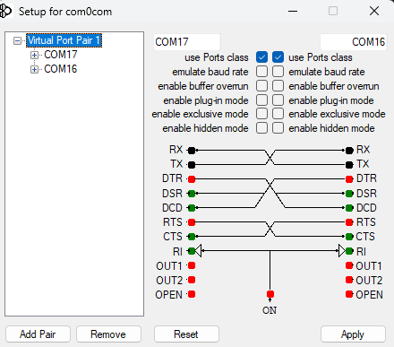
This example requires an SLCAN device such as the Zubax Babel and any software that can emulate COM ports. In this example, we are using com0com. Please note that the following example will only work on the Windows operating system, though a similar approach can be taken on Linux/UNIX.
Note
If com0com does not produce a numbered virtual COM port (as shown below), or if there is a warning in the device manager for the com0com serial port emulator, it is recommended to update your drivers by following this guide.
We will use the virtual COM ports in order to create the following connections:
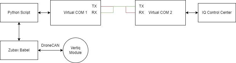
In order to create the required virtual COM ports using com0com, open com0com, and create a Virtual Port Pair. In this example, we’ve created COM16 and COM17 which, by default, are connected as depicted in the diagram above.
On Windows, you can confirm that these ports are reachable through Device Manager.

The Python script necessary to accomplish run this example is provided here. Run this script before attempting to connect with the Control Center:
import time
import iqmotion as iq
import dronecan
import serial

slcan_port = "COM9" #Replace this value with the port connected to your SLCAN device
control_center_ftdi_port = "COM17" # Replace this value with the port connected to a virtual COM port

def make_node():
        for attempt in range(10):
                try:
                        node = dronecan.make_node(slcan_port, node_id=126, baudrate=115200, bitrate=500000)
                except serial.SerialException:
                        print("Trouble connecting to DroneCAN, waiting and trying again...")
                        time.sleep(2)
                        continue
                else:
                        break

        return node

def read_response_callback(event):
        if event:
                data = event.transfer.payload.buffer
                decode_gotten_data(data)
        else:
                print("Read request has timed out")

def decode_gotten_data(data):
        received_iquart_data = []
        for byte in data:
                received_iquart_data.append(byte)

        packet_parse.add_to_out_queue(bytearray(received_iquart_data))
        packet_parse.send_now()

def crc16(data: bytes):
        '''
        CRC-16 (CCITT) implemented with a precomputed lookup table
        '''
        table = [
                0x0000, 0x1021, 0x2042, 0x3063, 0x4084, 0x50A5, 0x60C6, 0x70E7, 0x8108, 0x9129, 0xA14A, 0xB16B, 0xC18C, 0xD1AD,
                0xE1CE, 0xF1EF,
                0x1231, 0x0210, 0x3273, 0x2252, 0x52B5, 0x4294, 0x72F7, 0x62D6, 0x9339, 0x8318, 0xB37B, 0xA35A, 0xD3BD, 0xC39C,
                0xF3FF, 0xE3DE,
                0x2462, 0x3443, 0x0420, 0x1401, 0x64E6, 0x74C7, 0x44A4, 0x5485, 0xA56A, 0xB54B, 0x8528, 0x9509, 0xE5EE, 0xF5CF,
                0xC5AC, 0xD58D,
                0x3653, 0x2672, 0x1611, 0x0630, 0x76D7, 0x66F6, 0x5695, 0x46B4, 0xB75B, 0xA77A, 0x9719, 0x8738, 0xF7DF, 0xE7FE,
                0xD79D, 0xC7BC,
                0x48C4, 0x58E5, 0x6886, 0x78A7, 0x0840, 0x1861, 0x2802, 0x3823, 0xC9CC, 0xD9ED, 0xE98E, 0xF9AF, 0x8948, 0x9969,
                0xA90A, 0xB92B,
                0x5AF5, 0x4AD4, 0x7AB7, 0x6A96, 0x1A71, 0x0A50, 0x3A33, 0x2A12, 0xDBFD, 0xCBDC, 0xFBBF, 0xEB9E, 0x9B79, 0x8B58,
                0xBB3B, 0xAB1A,
                0x6CA6, 0x7C87, 0x4CE4, 0x5CC5, 0x2C22, 0x3C03, 0x0C60, 0x1C41, 0xEDAE, 0xFD8F, 0xCDEC, 0xDDCD, 0xAD2A, 0xBD0B,
                0x8D68, 0x9D49,
                0x7E97, 0x6EB6, 0x5ED5, 0x4EF4, 0x3E13, 0x2E32, 0x1E51, 0x0E70, 0xFF9F, 0xEFBE, 0xDFDD, 0xCFFC, 0xBF1B, 0xAF3A,
                0x9F59, 0x8F78,
                0x9188, 0x81A9, 0xB1CA, 0xA1EB, 0xD10C, 0xC12D, 0xF14E, 0xE16F, 0x1080, 0x00A1, 0x30C2, 0x20E3, 0x5004, 0x4025,
                0x7046, 0x6067,
                0x83B9, 0x9398, 0xA3FB, 0xB3DA, 0xC33D, 0xD31C, 0xE37F, 0xF35E, 0x02B1, 0x1290, 0x22F3, 0x32D2, 0x4235, 0x5214,
                0x6277, 0x7256,
                0xB5EA, 0xA5CB, 0x95A8, 0x8589, 0xF56E, 0xE54F, 0xD52C, 0xC50D, 0x34E2, 0x24C3, 0x14A0, 0x0481, 0x7466, 0x6447,
                0x5424, 0x4405,
                0xA7DB, 0xB7FA, 0x8799, 0x97B8, 0xE75F, 0xF77E, 0xC71D, 0xD73C, 0x26D3, 0x36F2, 0x0691, 0x16B0, 0x6657, 0x7676,
                0x4615, 0x5634,
                0xD94C, 0xC96D, 0xF90E, 0xE92F, 0x99C8, 0x89E9, 0xB98A, 0xA9AB, 0x5844, 0x4865, 0x7806, 0x6827, 0x18C0, 0x08E1,
                0x3882, 0x28A3,
                0xCB7D, 0xDB5C, 0xEB3F, 0xFB1E, 0x8BF9, 0x9BD8, 0xABBB, 0xBB9A, 0x4A75, 0x5A54, 0x6A37, 0x7A16, 0x0AF1, 0x1AD0,
                0x2AB3, 0x3A92,
                0xFD2E, 0xED0F, 0xDD6C, 0xCD4D, 0xBDAA, 0xAD8B, 0x9DE8, 0x8DC9, 0x7C26, 0x6C07, 0x5C64, 0x4C45, 0x3CA2, 0x2C83,
                0x1CE0, 0x0CC1,
                0xEF1F, 0xFF3E, 0xCF5D, 0xDF7C, 0xAF9B, 0xBFBA, 0x8FD9, 0x9FF8, 0x6E17, 0x7E36, 0x4E55, 0x5E74, 0x2E93, 0x3EB2,
                0x0ED1, 0x1EF0
                ]

        crc = 0xFFFF
        for byte in data:
                crc = (crc << 8) ^ table[(crc >> 8) ^ byte]
                crc &= 0xFFFF  # important, crc must stay 16bits all the way through
        return crc

if __name__ == "__main__":
        #Create an object that can create/parse IQUART mesages
        packet_parse = iq.SerialCommunicator(control_center_ftdi_port)

        #Create a DroneCAN node, and start it up
        dronecan_node = make_node()

        #Add a callback function for when we receive Tunnel Broadcast mesasges
        dronecan_node.add_handler(dronecan.uavcan.tunnel.Broadcast, read_response_callback)

        while(1):
                #Process our DroneCAN node
                dronecan_node.spin(0)

                #If we got IQUART data, package it for DroneCAN and send it out
                packet_parse.read_bytes()
                message_byte_arr = packet_parse.extract_message()
                if(message_byte_arr is not None):
                        buffer_to_send = list(packet_parse._make_packet(message_byte_arr))
                        message = dronecan.uavcan.tunnel.Broadcast(protocol=dronecan.uavcan.tunnel.Protocol(protocol=0x55), channel_id=42, buffer=buffer_to_send)
                        dronecan_node.broadcast(message)
While this script is running, your module is powered on and connected properly, and your virtual COM ports are configured correctly, you should be able to connect your module to IQ Control Center without a direct serial connection.
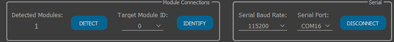
With the script active, navigate to the Control Center, and in Serial Port, select the virtual COM port not connected to your running script (in this case COM16). After you click CONNECT, you should see the Control Center perform its normal detection process, and connect with your module.
Refer to the uavcan.tunnel.Broadcast section of Standard Data Types in the specification for more details.
uavcan.equipment.safety.ArmingStatus (Data Type ID = 1100)
Speed Firmware Support |
Servo Firmware Support |
|---|---|
Yes |
No |
Note
The ArmingStatus message is not yet supported on all modules that support DroneCAN. Please check vertiq.co to ensure that you are on the latest firmware version available for your module to gain access to the most up to date features.
DroneCAN’s ArmingStatus message broadcasts the overall system’s arming state. For example, both PX4 and ArduPilot can transmit the ArmingStatus message. Vertiq modules are configured only to listen for, and not transmit, the ArmingStatus message. More information on configuring your module to update its arming state based on the ArmingStatus message can be found below in Arming and Arming Bypass. Information about configuring your flight controller to transmit the ArmingStatus message can be found in our tutorial for integrating with flight controller DroneCAN.
uavcan.equipment.indication.LightsCommand (Data Type ID = 1081)
Speed Firmware Support |
Servo Firmware Support |
|---|---|
Yes |
Yes (v0.1.0 and later) |
Vertiq modules do not publish this broadcast message, but they do listen for it. The content of this message can be used to dynamically control the white and RGB LEDs on Vertiq’s LED Boards. For more information on the LED Board, see Stock LED Support (White and RGB LED Control).
As detailed by the DroneCAN specification this message contains an array of SingleLightCommands to be handled by the nodes on the bus. Each SingleLightCommand contains a light ID to indicate which light that command is for and a field that indicates either the intensity of the white LED or the color of the RGB LED depending on the targeted LED. For Vertiq modules, the light ID of each type of LED (RGB or White) is determined based on the ESC index (or Actuator ID if using servo firmware v0.1.0 or newer). This allows the LEDs on each module on a bus to be uniquely addressable as long as each module has a unique ESC index (or Actuator ID). The light IDs on each module are calculated as described in the example code blocks below:
For speed firmware:
#The base ID for an RGB LED is 1, and the base ID for a white LED is 2. From there, we can just apply the calculation below to determine
#what the light IDs for a module with a given ESC index should be. For example, if my module has an ESC Index of 1,
#then the White LED's light ID will be 1*3 + 2 = 5. The RGB LED's light ID will be 1*3+1 = 4
RGB_LIGHT_TYPE_BASE_ID = 1
WHITE_LIGHT_TYPE_BASE_ID  = 2

light_id = (esc_index*3 + LIGHT_TYPE_BASE_ID)
For servo firmware:
#The base ID for an RGB LED is 1, and the base ID for a white LED is 2. From there, we can just apply the calculation below to determine
#what the light IDs for a module with a given Actuator ID should be. For example, if my module has an Actuator ID of 1,
#then the White LED's light ID will be 1*3 + 2 = 5. The RGB LED's light ID will be 1*3+1 = 4
RGB_LIGHT_TYPE_BASE_ID = 1
WHITE_LIGHT_TYPE_BASE_ID  = 2

light_id = (actuator_id*3 + LIGHT_TYPE_BASE_ID)
Refer to the uavcan.equipment.indication.LightsCommand section of Standard Data Types in the specification for more details.
uavcan.equipment.esc.StatusExtended (Data Type ID = 1036)
Speed Firmware Support |
Servo Firmware Support |
|---|---|
Yes |
No |
Note
This message is published only if DroneCAN Telemetry Style is configured to Use New-Style Telemetry. More information about telemetry style is found below.
This message is published periodically, and acts as an extension of uavcan.equipment.esc.Status. The extra information in this message is as follows:
Input Percent: Input command to ESC, in percent, which is commanded using the setpoint messages. Range 0% to 100%
Output Percent: Output command from ESC to motor, in percent. Range 0% to 100%
Motor Temperature °C: Temperature of connected motor, in Celsius. Range is -256 to +255 C
Motor Angle: Measured angle of connected angle sensor, in degrees. Range is 0 to 360
- Status Flags: Manufacturer-specific status flags currently active
Bit 0: Indicates the module’s current arming state (see Advanced Arming for more information)
Bits [3:1]: Indicate the module’s drive mode (see brushless drive’s
drive_modefor more information)Bit 4: Indicates if the module is timed out (see Timeout for more)
Bit 5: Indicates if the last stow attempt was successful (see Stow Position for more information)
Bit 6: Indicates if the module is holding stow (see Stow Position for more information)
Bits [8:7]: Indicates the throttle source currently driving the motor (see Monitoring the Active Throttle Source for more information)
ESC Index: The ESC index of the motor that is broadcasting this update
The frequency that this message is published at is determined by the Telemetry Frequency configuration parameter.
Please note that it is possible to disable this message, and fall back to the legacy transmission of uavcan.equipment.esc.Status and uavcan.equipment.device.Temperature as your
telemetry sources. In IQ Control Center’s Advanced tab, you’ll find the DroneCAN Telemetry Style parameter.

Setting this to Use New-Style Telemetry will output ESC Status and ESC Status Extended as your telemetry. In this case, the reported temperature through ESC Status is
your module’s microcontroller temperature in Kelvin, and ESC Status Extended’s reported temperature is the temperature of your module’s coils in °C.
Setting this to Use Old-Style Telemetry will output ESC Status and Device Temperature as your telemetry. In this case, the reported temperature through ESC Status
is your module’s coil temperature in Kelvin, and Device Temperature’s reported temperature is the temperature of your module’s microcontroller in Kelvin.
Note
We recommend using the Use New-Style Telemetry in order to receive the most telemetry data from your modules.
uavcan.equipment.actuator.ArrayCommand (Data Type ID: 1010)
Speed Firmware Support |
Servo Firmware Support |
|---|---|
No |
Yes (v0.1.0 and later) |
This message is used to control modules configured as actuators. This message should be broadcast to your module(s), and is typically the message that a flight controller will transmit. Each ArrayCommand message can contain up to 15 individual Command instances.
All Command instances contain 3 important pieces of information: the target actuator ID, the type of command, and the command value. In order to control your module with
ArrayCommand messages, you must properly set its actuator_id parameter. You can find more information on this below.
Vertiq modules accept 2 Command types: unitless and position. Unitless commands (type 0) are those most often used by flight controllers, and transmit values between [-1, 1].
Vertiq modules can be configured to treat unitless commands as PWM, voltage, velocity, angular displacement, or linear displacement commands. This configuration is available
under unitless_control_mode which is explained in depth below.
Once a type is selected, the actual response is defined by the unitless_control_minimum and unitless_control_maximum parameters. As an example, suppose you have
configured unitless_control_mode to 3 (angular displacement), your unitless_control_minimum to -3.14, and your unitless_control_maximum to 20.
This means that a unitless actuator command value of -1 will command your module to -3.14 rad, and a command value of 1 commands your module to 20 rad. Now, suppose
you change your control mode to 2 (velocity). A command value of -1 now maps to -3.14 rad/s, and 1 to 20 rad/s.
The positional example is illustrated below, and uses the DroneCAN GUI tool’s Actuator Panel to send commands. To access the Actuator Panel, navigate to Panels > Actuator Panel:
Direct position control actuator commands (type 1) directly send a control angular displacement value to the module. Suppose you transmit a Command for your module’s actuator ID with command type 1 and value -26. This will command your module to an angular displacement of -26 rad.
This type is not generally transmitted by flight controllers. It can, however, be easily tested through the DroneCAN GUI Tool’s Interactive Console. Navigate to Tools > Interactive Console.
Note
Please note that this example can be similarly executed through the PyDroneCAN library as the DroneCAN GUI’s Interactive Console is simply a wrapper around a DroneCAN node created through PyDroneCAN.
You can use the following commands in order to command your module to an angular displacement of 20 rad. Make sure to replace the actuator_id with your module’s configured actuator ID, and command_value to the desired displacement:
cmd_message = dronecan.uavcan.equipment.actuator.ArrayCommand()
position = dronecan.uavcan.equipment.actuator.Command()
position.command_type = 1
position.command_value = 20
position.actuator_id = 0
cmd_message.commands = [position]
node.broadcast(cmd_message)
Refer to the uavcan.equipment.actuator.ArrayCommand section of Standard Data Types in the specification for more details.
uavcan.equipment.actuator.Status (Data Type ID: 1011)
Speed Firmware Support |
Servo Firmware Support |
|---|---|
No |
Yes (v0.1.0 and later) |
Actuator status is telemetry sent out by Vertiq actuators. It provides your module’s current actuator ID, position as angular displacement, current velocity, and power rating.
This message is sent by your module at a rate as defined by telemetry_frequency.
Vertiq modules do not transmit force, and fill in NaN to the force field as specified by the DroneCAN standard.
Refer to the uavcan.equipment.actuator.Status section of Standard Data Types in the specification for more details.
Service Requests
Service requests are messages sent to a specific target node from another node, and to which the sending node expects to receive a response message.
uavcan.protocol.GetNodeInfo (Data Type ID = 1)
Speed Firmware Support |
Servo Firmware Support |
|---|---|
Yes |
Yes (v0.1.0 and later) |
This request has no payload fields. The response message from the receiving node should include the status of the node as defined by the NodeStatus message, the software and hardware version of the node, and the name of the node. For Vertiq modules, the name of each node is currently “iq_motion.esc”.
Refer to the uavcan.protocol.GetNodeInfo section of Standard Data Types in the specification for more details
uavcan.protocol.dynamic_node_id.Allocation (Data Type ID = 1)
Speed Firmware Support |
Servo Firmware Support |
|---|---|
Yes |
Yes (v0.1.0 and later) |
This message is used by both the dynamic node allocator and allocatee. Vertiq modules can only act as the DNA allocatee. It is used to carry out the DNA process which is covered in detail here. More information about configuring your Vertiq module to use dynamic node ID allocation, please refer to Advanced Plug-And-Play Functionality.
Refer to The uavcan.protocol.dynamic_node_id.Allocation section of the Standard Data Types in the specification for more details on this message.
uavcan.protocol.param.GetSet (Data Type ID = 11)
Speed Firmware Support |
Servo Firmware Support |
|---|---|
Yes |
Yes (v0.1.0 and later) |
Used to get or set the value of a configuration parameter using either the index or the name of the parameter. The configuration parameters currently available on standard Vertiq modules are listed in the Configuration Parameters section below. The request message should contain the index or name of the parameter (depending on how you are accessing it), and if performing a set operation, should contain the value to set to the parameter. Parameter indices are not guaranteed to remain consistent across firmware versions. Indices should only be used for parameter discovery, when accessing the parameter directly it is recommended to always use the name.
The response message will contain the value of the parameter, information about its default, minimum, and maximum values (if applicable), and the name of the parameter.
Refer to the uavcan.protocol.param.GetSet section of Standard Data Types in the specification for more details.
uavcan.protocol.RestartNode (Data Type ID = 5)
Speed Firmware Support |
Servo Firmware Support |
|---|---|
Yes |
Yes (v0.1.0 and later) |
This request has one field, its “magic number.” This field is an unsigned 40 bit integer. The magic number is used to identify that this is an intentional restart request, and we have also extended it to allow for two different types of reboots. One magic number performs a normal reboot that simply restarts into the normal application firmware, and the other reboots the device into the ST bootloader, which allows it to be programmed with new firmware. The numbers for each are:
Normal Reboot Magic Number = 0xACCE551B1E
Reboot to Bootloader Magic Number = 0xBEEFCAFE
The response to this request contains one boolean field. This field will be true if the number received was a valid magic number and the motor is restarting, and false if the number received was not one of the valid numbers.
Refer to the uavcan.protocol.RestartNode section of Standard Data Types in the specification for more details.
uavcan.protocol.file.BeginFirmwareUpdate (Data Type ID = 40)
Speed Firmware Support |
Servo Firmware Support |
|---|---|
Yes |
Yes (v0.1.0 and later) |
On modules that support DroneCAN firmware updates, this command causes the module to enter into upgrade mode, and begin attempting to firmware update over DroneCAN. The request includes a source node ID and a file path on that source node. The module will attempt to get information on the file from the file server, and then begin reading the data from the upgrade file.
On modules that do not support DroneCAN firmware updates, the module will respond with an INVALID_MODE error code to this request.
Refer to the uavcan.protocol.file.BeginFirmwareUpdate section of Standard Data Types in the specification for more details.
Configuration Parameters
Configuration parameters are parameters that can configure the behavior of a Vertiq module and are available to read and modify over DroneCAN. The uavcan.protocol.param.GetSet request can be used to access configuration parameters. The sections below cover the stadard configuration parameters available on Vertiq modules.
Node ID
Name |
Type |
Speed Firmware Support |
Servo Firmware Support |
|---|---|---|---|
uavcan_node_id |
Integer |
Yes |
Yes (v0.1.0 and later) |
This parameter defines the node ID of the module on the UAVCAN network. This ID is how the node identifies itself when sending and receiving messages. No two nodes should have the same node ID. ID 0 is reserved by the DroneCAN standard for unconfigured modules. A reboot is typically required after changing this parameter for the device to use the new node ID on the network.
This parameter can also be changed through the IQ Control Center if you wish to change this without using DroneCAN.
Bitrate
Name |
Type |
Speed Firmware Support |
Servo Firmware Support |
|---|---|---|---|
bit_rate |
Integer |
Yes |
Yes (v0.1.0 and later) |
This parameter determines the DroneCAN bitrate that the module will use in bit/s. This parameter takes effect immediately when changed, so if this is changed it will most likely be necessary to reconnect to the bus as at the new bitrate to continue communicating with the module.
ESC Index
Name |
Type |
Speed Firmware Support |
Servo Firmware Support |
|---|---|---|---|
esc_index |
Integer |
Yes |
No |
This parameter defines the ESC index of the module. The ESC index is used when a Raw Command message is received to determine which value in the Raw Command should be read by the module.
This parameter can also be changed through the IQ Control Center if you wish to change this without using DroneCAN.
Zero Behavior
Name |
Type |
Speed Firmware Support |
Servo Firmware Support |
|---|---|---|---|
zero_behavior |
Integer |
Yes |
No |
This parameter defines the behavior of the motor when it receives a zero setpoint in a Raw Command message, but only if the module is bypassing arming on DroneCAN. If the module is using normal arming with DroneCAN, the Zero Behavior is not used, instead the disarm behavior provides a similar functionality that integrates with arming and disarming.
There are three possible behaviors: Coast, Brake, and Normal Controller. By changing the integer value of Zero Behavior, the user can determine which of these behaviors is used.
Descriptions of each behavior and the integer value of the Zero Behavior parameter corresponding to them are given below:
Coast (Value = 0): The module will stop trying to drive the motor, releasing control and letting it simply coast to a stop.
Brake (Value = 1): The motor will stop suddenly on a zero setpoint instead of coasting gently to a stop. After stopping, it will then coast.
Normal Controller (Value = 2): The normal controller continues to run, and will try to drive the motor at 0% throttle. This can cause vibrating or twitching in velocity mode if the PID gains are high.
This parameter can also be changed through the IQ Control Center if you wish to change this without using DroneCAN.
Telemetry Frequency
Name |
Type |
Speed Firmware Support |
Servo Firmware Support |
|---|---|---|---|
telem_frequency |
Integer |
Yes |
Yes (v0.1.0 and later) |
This parameter defines the frequency in Hz with which the telemetry messages (uavcan.equipment.esc.Status and uavcan.equipment.device.Temperature) are broadcast by the module. For example, if this value were set to 10, the telemetry would be sent at a rate of 10 Hz. If this parameter is set to 0, no telemetry messages will be sent.
This parameter can also be changed through the IQ Control Center if you wish to change this without using DroneCAN.
Motor Armed
Name |
Type |
Speed Firmware Support |
Servo Firmware Support |
|---|---|---|---|
motor_armed |
Integer |
Yes |
No |
This parameter is available on modules that support Advanced Arming. It can be used to query and control the armed state of the module. See the section on user arming commands over DroneCAN for more information.
Motor Stowed
Name |
Type |
Speed Firmware Support |
Servo Firmware Support |
|---|---|---|---|
motor_stowed |
Integer |
Yes |
No |
This parameter is available on modules that support Stow Position. It can be used to command and release stow on modules. See the section on manual stow over DroneCAN for more information.
Stow Status
Name |
Type |
Speed Firmware Support |
Servo Firmware Support |
|---|---|---|---|
stow_status |
Integer |
Yes |
No |
This parameter is available on modules that support Stow Position. It reports on the current state of the stow feature on the module. See the Stow Status section for more information.
Stow Result
Name |
Type |
Speed Firmware Support |
Servo Firmware Support |
|---|---|---|---|
stow_result |
Integer |
Yes |
No |
This parameter is available on modules that support Stow Position. It reports on how the previous stow attempt ended. See the Stow Result section for more information.
Module ID
Name |
Type |
Speed Firmware Support |
Servo Firmware Support |
|---|---|---|---|
module_id |
Integer |
Yes (v0.2.1 and later) |
Yes (v0.1.0 and later) |
This parameter defines the module ID of the connected module. Please note that this is different than the DroneCAN Node ID. Your module’s Module ID parameter defines what IQUART messages to accept. You can find out more about IQUART at IQUART, and more about connecting to multiple modules via IQUART in our IQ Control Center documentation.
Motor Direction
Name |
Type |
Speed Firmware Support |
Servo Firmware Support |
|---|---|---|---|
motor_direction |
Integer |
Yes (v0.2.1 and later) |
No |
Your module’s motor direction defines, in part, how your module will interpret and react to throttle commands. Motor direction is covered in detail in our throttle documentation.
Motor direction is enumerated as:
Unconfigured
3D Counter Clockwise
3D Clockwise
2D Counter Clockwise
2D Clockwise
Please note that if you are controlling your module with DroneCAN throttle commands, the 3D-2D distinction has no effect. All DroneCAN throttles are taken to be signed (3D),
and motor_direction affects only whether positive throttles specify clockwise or counter clockwise spinning. For more on throttle mapping, see Mapping to Throttle.
Control Mode
Name |
Type |
Speed Firmware Support |
Servo Firmware Support |
|---|---|---|---|
control_mode |
Integer |
Yes (v0.2.1 and later) |
No |
Mode determines how the module interprets received throttle commands, and is covered in detail at Mode.
Control mode is enumerated as:
PWM
Voltage
Velocity
Max Volts
Name |
Type |
Speed Firmware Support |
Servo Firmware Support |
|---|---|---|---|
max_volts |
Float |
Yes (v0.2.1 and later) |
No |
When control_mode is configured to voltage, max_volts defines the maximum allowable driving voltage. More information can be found at Maximum Voltage.
Max Velocity
Name |
Type |
Speed Firmware Support |
Servo Firmware Support |
|---|---|---|---|
max_velocity |
Float |
Yes (v0.2.1 and later) |
No |
When control_mode is configured to velocity, max_velocity defines the maximum allowable angular velocity in rad/s. More information can be found at Maximum Velocity.
Arm with ArmingStatus
Name |
Type |
Speed Firmware Support |
Servo Firmware Support |
|---|---|---|---|
arm_with_arming_status |
Integer |
Yes (v0.2.1 and later) |
No |
Determines whether the module will arm and disarm based on the DroneCAN Arming Status message. A value of 0 disables arming with the ArmingStatus message, and a value of 1 enables it. More information can be found at Arming with ArmingStatus
Communication Timeout
Name |
Type |
Speed Firmware Support |
Servo Firmware Support |
|---|---|---|---|
communication_timeout |
Float |
Yes (v0.2.1 and later) |
No |
Sets the communication timeout period of the module. See Timeout for more information.
Arm on Throttle
Name |
Type |
Speed Firmware Support |
Servo Firmware Support |
|---|---|---|---|
arm_on_throttle |
Integer |
Yes (v0.2.1 and later) |
No |
Determines whether the module will arm based on incoming throttles. A value of 0 disables arming on throttles, and a value of 1 enables arming on throttles. For more information on this parameter and arming with throttles, see Arming With the Arming Throttle Regions.
Arming Throttle Upper Limit
Name |
Type |
Speed Firmware Support |
Servo Firmware Support |
|---|---|---|---|
arming_throttle_upper_limit |
Float |
Yes (v0.2.1 and later) |
No |
Determines the upper limit of the arming throttle region. This parameter is defined in terms of per-unit of throttle. For example, a value of 0.05 corresponds to 5% throttle. For more information on this parameter and arming with throttles, see Arming With the Arming Throttle Regions.
Arming Throttle Lower Limit
Name |
Type |
Speed Firmware Support |
Servo Firmware Support |
|---|---|---|---|
arming_throttle_lower_limit |
Float |
Yes (v0.2.1 and later) |
No |
Determines the lower limit of the arming throttle region. This parameter is defined in terms of per-unit of throttle. For example, a value of 0.05 corresponds to 5% throttle. For more information on this parameter and arming with throttles, see Arming With the Arming Throttle Regions.
Disarm on Throttle
Name |
Type |
Speed Firmware Support |
Servo Firmware Support |
|---|---|---|---|
disarm_on_throttle |
Integer |
Yes (v0.2.1 and later) |
No |
Determines whether the module will disarm based on incoming throttles. A value of 0 disables disarming on throttles, and a value of 1 enables disarming on throttles. For more information on this parameter and disarming with throttles, see Disarming With the Disarming Throttle Region.
Disarming Throttle Upper Limit
Name |
Type |
Speed Firmware Support |
Servo Firmware Support |
|---|---|---|---|
disarming_throttle_upper_limit |
Float |
Yes (v0.2.1 and later) |
No |
Determines the upper limit of the disarming throttle region. This parameter is defined in terms of per-unit of throttle. For example, a value of 0.05 corresponds to 5% throttle. For more information on this parameter and disarming with throttles, see Disarming With the Disarming Throttle Region.
Disarming Throttle Lower Limit
Name |
Type |
Speed Firmware Support |
Servo Firmware Support |
|---|---|---|---|
disarming_throttle_lower_limit |
Float |
Yes (v0.2.1 and later) |
No |
Determines the lower limit of the disarming throttle region. This parameter is defined in terms of per-unit of throttle. For example, a value of 0.05 corresponds to 5% throttle. For more information on this parameter and disarming with throttles, see Disarming With the Disarming Throttle Region.
Disarm Behavior
Name |
Type |
Speed Firmware Support |
Servo Firmware Support |
|---|---|---|---|
disarm_behavior |
Integer |
Yes (v0.2.1 and later) |
No |
Determines how the module will stop when it disarms. For more information on this parameter and descriptions of how each behavior works, see Disarming Behavior.
To determine the disarm behavior, set this parameter to the proper integer for the desired behavior. Disarm behavior is enumerated as:
Coast
0V to Coast
0V to Brake
Stow
Disarm Song Option
Name |
Type |
Speed Firmware Support |
Servo Firmware Support |
|---|---|---|---|
disarm_song_option |
Integer |
Yes (v0.2.1 and later) |
No |
Determines if and how many times the module will play its disarm song after coming to a stop. For more information on this parameter and its options, see Disarming Song Playback Options.
To determine the disarm song option, set this parameter to the proper integer for the desired option. Disarm song option is enumerated as:
Never Play
Play Once
Play Continuously
Hold Stow
Name |
Type |
Speed Firmware Support |
Servo Firmware Support |
|---|---|---|---|
hold_stow |
Integer |
Yes (v0.2.1 and later) |
No |
Determines if and how the module will attempt to hold its position after stowing. For more information on this parameter and its options, see Hold Stow.
To determine the hold stow behavior, set this parameter to the proper integer for the desired behavior. Hold stow behavior is enumerated as:
Coast
Hold Stow
Brake
Low Power Hold Stow
Stow Target Angle
Name |
Type |
Speed Firmware Support |
Servo Firmware Support |
|---|---|---|---|
stow_target_angle |
Float |
Yes (v0.2.1 and later) |
No |
Determines the stow target angle, as described in Stow Angle Parameters. For more information on stowing and the effect of this parameter on the angle, see Stow Position and Stow Position Calculation.
Sample Stow Zero Angle
Name |
Type |
Speed Firmware Support |
Servo Firmware Support |
|---|---|---|---|
sample_stow_zero_angle |
Integer |
Yes (v0.2.1 and later) |
No |
Allows users to sample and save the stow zero angle. For more information on the stow zero angle and what it means to sample it, see Stow Angle Parameters and Stow Position Calculation.
Setting this parameter to 1 will trigger the module to sample and save its current angle as the zero angle. After setting it to 1 and sampling the angle, sample_stow_zero_angle will automatically reset itself to 0 to show that it is ready for another sampling.
Stow Target Acceleration
Name |
Type |
Speed Firmware Support |
Servo Firmware Support |
|---|---|---|---|
stow_target_acceleration |
Float |
Yes (v0.2.1 and later) |
No |
Determines the stow target acceleration of the module when stowing. For more information on the stow target acceleration, see Stow Movement Parameters .
Unitless Control Mode
Name |
Type |
Speed Firmware Support |
Servo Firmware Support |
|---|---|---|---|
unitless_control_mode |
Integer |
No |
Yes (v0.1.0 and later) |
Determines what type of control should be used when controlling your module with Actuator ArrayCommands of the Unitless type. The options are voltage percentage, voltage, velocity, and position. Unitless commands are treated the same as Raw Value commands sent through the Servo Input parser. You can read more about raw inputs to the Servo Input Parser here.
An important difference from raw inputs is that ArrayCommand unitless commands are in the range [-1, 1] where raw commands are [0, 1]. In order to map correctly, ArrayCommand values are first mapped onto the [0, 1] range.
Suppose that your control mode is set to velocity, your unitless control minimum to -10, and your unitless control maximum to 10. Your module receives a unitless command with the value of -0.5. This is the equivalent of a raw command value of 0.25 which results in a velocity command of -5 rad/s.
Unitless Control Minimum
Name |
Type |
Speed Firmware Support |
Servo Firmware Support |
|---|---|---|---|
unitless_control_minimum |
Float |
No |
Yes (v0.1.0 and later) |
Determines the minimum actuation value when controlling your module with Actuator ArrayCommands of the Unitless type. The resulting action is dependent on your configured Unitless Control Mode. For example, suppose your control mode is set to position. If your unitless control minimum is set to -26, then an actuator command of -1 will move your module to a displacement of -26 rad (26 rad in the clockwise direction).
Unitless Control Maximum
Name |
Type |
Speed Firmware Support |
Servo Firmware Support |
|---|---|---|---|
unitless_control_maximum |
Float |
No |
Yes (v0.1.0 and later) |
Determines the maximum actuation value when controlling your module with Actuator ArrayCommands of the Unitless type. The resulting action is dependent on your configured Unitless Control Mode. For example, suppose your control mode is set to voltage. If your unitless control maximum is set to 5, then an actuator command of 1 will spin your module counter clockwise with a 5V command.
Warning Status Enable Bitmask
Name |
Type |
Speed Firmware Support |
Servo Firmware Support |
|---|---|---|---|
warning_status_enable_bitmask |
Integer |
Yes (v0.3.0 and later) |
Yes (v0.1.0 and later) |
Determines which of the warning health checks should be used. Warning health checks are used to update the value of the node health field of your module’s
reported Node Status to HEALTH_WARNING when your module is in neither an error nor critical state. Setting a bitmask value of 1 enables the warning check,
and a value of 0 disables the check.
The bits are laid out as follows:
Bit 0: Enable coil temperature warning
Bit 1: Enable microcontroller temperature warning
Bit 2: Enable over voltage warning
So, a value of 5 will have the coil temperature and over voltage warnings enabled, and the microcontroller temperature warning disabled.
If a warning is disabled, it will not be checked, and will always return a healthy result. So, setting this bitmask to 0 effectively disables all warning health checks.
Error Status Enable Bitmask
Name |
Type |
Speed Firmware Support |
Servo Firmware Support |
|---|---|---|---|
error_status_enable_bitmask |
Integer |
Yes (v0.3.0 and later) |
Yes (v0.1.0 and later) |
Determines which of the error health checks should be used. Error health checks are used to update the value of the node health field of your module’s
reported Node Status to HEALTH_ERROR when your module is not in a critical state. Setting a bitmask value of 1 enables the error check, and a value of 0
disables the check.
The bits are laid out as follows:
Bit 0: Enable timeout error
Bit 1: Enable derate error
So, a value of 1 will enable the timeout error check and disable the derate error check.
If an error is disabled, it will not be checked, and will always return a healthy result. So, setting this bitmask to 0 effectively disables all error health checks.
Critical Status Enable Bitmask
Name |
Type |
Speed Firmware Support |
Servo Firmware Support |
|---|---|---|---|
criticial_status_enable_bitmask |
Integer |
Yes (v0.3.0 and later) |
Yes (v0.1.0 and later) |
Determines which of the critical health checks should be used. Critical health checks are used to update the value of the node health field of your module’s
reported Node Status to HEALTH_CRITICAL. Setting a bitmask value of 1 enables the critical check, and a value of 0 disables the check.
The bits are laid out as follows:
Bit 0: Enable derate critical
Bit 1: Enable drive lockout critical
So, a value of 2 will enable the drive lockout critical check and disable the derate critical check.
If a critical check is disabled, it will not be checked, and will always return a healthy result. So, setting this bitmask to 0 effectively disables all critical health checks.
Actuator ID
Name |
Type |
Speed Firmware Support |
Servo Firmware Support |
|---|---|---|---|
actuator_id |
Integer |
No |
Yes (v0.1.0 and later) |
Determines what actuator ID your module will accept commands for when controlling your module with Actuator ArrayCommands.
Your module will only respond to commands when the provided actuator_id in the command matches your module’s configured ID.
An important note is that if multiple commands are received in a single ArrayCommand with the same target actuator ID, the module will only respond to the command received last.
Timeout Behavior
Name |
Type |
Speed Firmware Support |
Servo Firmware Support |
|---|---|---|---|
timeout_behavior |
Integer |
Yes (v0.3.0 and later) |
No |
Determines how your module will react after reaching a communication timeout. You can read more about your choices in our timeout documentation.
Timeout Song Playback Option
Name |
Type |
Speed Firmware Support |
Servo Firmware Support |
|---|---|---|---|
timeout_song_playback_option |
Integer |
Yes (v0.3.0 and later) |
No |
Determines what kind of playback option your module will execute after reaching a communication timeout. You can read more about your choices in our timeout documentation.
Play Arming Song On Arm
Name |
Type |
Speed Firmware Support |
Servo Firmware Support |
|---|---|---|---|
play_arming_song_on_arm |
Integer |
Yes (v0.3.0 and later) |
No |
Determines whether or not your module will play its arming song on an arming transition. Setting this value to 0 disables the song playback, 1 enables it.
DroneCAN Bypass Arming
Name |
Type |
Speed Firmware Support |
Servo Firmware Support |
|---|---|---|---|
dronecan_bypass_arming |
Integer |
Yes (v0.3.0 and later) |
No |
Determines whether or not your module is subject to arming as defined by the arming handler. If this value is set to 1, then all DroneCAN Raw Commands are applied to spin your module without regards for the module’s arming state. You can read more about this in Arming and Arming Bypass.
DroneCAN Telemetry Style
Name |
Type |
Speed Firmware Support |
Servo Firmware Support |
|---|---|---|---|
dronecan_telemetry_style |
Integer |
Yes (v0.3.0 and later) |
No |
Specifies the style of telemetry that your DroneCAN node will report. If set to 0, your module will transmit the ESC Status and ESC Status Extended messages. When set to 1, your module will transmit ESC Status and Device Temperature. More information on the different telemetry styles is discussed below.
Tip
We recommend setting this parameter to 0 (using ESC Status and ESC Status Extended) unless the use of the Device Temperature message is absolutely necessary.
ESC Status Error Count Meaning
Name |
Type |
Speed Firmware Support |
Servo Firmware Support |
|---|---|---|---|
esc_status_error_meaning |
Integer |
Yes (v0.3.0 and later) |
No |
Defines how the module calculates the reported error count in its ESC Status telemetry data.
Note
CAN TX or RX errors are defined at the CAN bus protocol level, and are not directly related to DroneCAN. They are used to monitor your CAN bus’s fidelity. More information about CAN bus errors and how they are updated by the hardware can be found here.
There are 5 error count options:
Active CAN TX errors (the value of TEC)
Active CAN RX errors (the value of REC)
Maximum of TEC and REC
A logical OR combination of TEC | REC. Combined, the value is a 32-bit number whose top 16 bits represent TECE, and the bottom 16 REC
The cumulative number of both TEC and REC errors since module power on
RGB LED Strobe Enable
Name |
Type |
Speed Firmware Support |
Servo Firmware Support |
|---|---|---|---|
rgb_led_strobe_active |
boolean |
Yes (v0.3.0 and later) |
No |
Defines whether or not the RGB LED on your connected Vertiq LED board should strobe according to its strobing settings or should remain on statically. Set this value to true to enable strobing, false otherwise. You can read more about strobing and its configurations in our LED documentation.
RGB LED Strobe Period
Name |
Type |
Speed Firmware Support |
Servo Firmware Support |
|---|---|---|---|
rgb_led_strobe_period |
float |
Yes (v0.3.0 and later) |
No |
Defines, in seconds, the length of your configured RGB LED strobing pattern. You can find more information about LED strobing period configuration in Strobing Period.
RGB LED Strobe Pattern
Name |
Type |
Speed Firmware Support |
Servo Firmware Support |
|---|---|---|---|
rgb_led_strobe_pattern |
Integer |
Yes (v0.3.0 and later) |
No |
Defines the strobing pattern of your RGB LED as a 32-bit bitmask. Each bit represents 1/32 of the total LED strobing period. A 1 in the bitmask represents that the LED should be on during that portion of the strobing pattern, a 0 turns off the LED. More information about strobing patterns is found in Strobing Pattern.
White LED Strobe Enable
Name |
Type |
Speed Firmware Support |
Servo Firmware Support |
|---|---|---|---|
white_led_strobe_active |
boolean |
Yes (v0.3.0 and later) |
No |
Defines whether or not the white LED on your connected Vertiq LED board should strobe according to its strobing settings or should remain on statically. Set this value to true to enable strobing, false otherwise. You can read more about strobing and its configurations in our LED documentation.
White LED Strobe Period
Name |
Type |
Speed Firmware Support |
Servo Firmware Support |
|---|---|---|---|
white_led_strobe_period |
float |
Yes (v0.3.0 and later) |
No |
Defines, in seconds, the length of your configured white LED strobing pattern. You can find more information about LED strobing period configuration in Strobing Period.
White LED Strobe Pattern
Name |
Type |
Speed Firmware Support |
Servo Firmware Support |
|---|---|---|---|
white_led_strobe_pattern |
Integer |
Yes (v0.3.0 and later) |
No |
Defines the strobing pattern of your white LED as a 32-bit bitmask. Each bit represents 1/32 of the total LED strobing period. A 1 in the bitmask represents that the LED should be on during that portion of the strobing pattern, a 0 turns off the LED. More information about strobing patterns is found in Strobing Pattern.
Flight Controller Integration
For guidance on integrating Vertiq modules with flight controllers using DroneCAN, see the DroneCAN Integration with PX4 and ArduPilot tutorial.
Arming and Arming Bypass
Standard Arming
DroneCAN can use the same advanced arming procedure as all other throttle sources. The details of this arming procedure are covered in the Advanced Arming section.
Arming with ArmingStatus
Vertiq modules can arm and disarm based off of DroneCAN’s ArmingStatus message. This means that whenever your flight controller broadcasts an ArmingStatus
STATUS_FULLY_ARMED message, your module will transition from disarmed to armed, or if already armed, will remain armed. These transitions are not subject to the constraints
set by your arming throttle region, so any STATUS_FULLY_ARMED message will arm your module. When your flight controller broadcasts a STATUS_DISARMED message, your module
will similarly transition from armed to disarmed.
Whether your module arms via the ArmingStatus message is configured through the arming_by_arming_status parameter in the DroneCAN node client. You can access this parameter through
the Control Center’s Advanced tab as Arming By DroneCAN ArmingStatus.

This parameter can also be configured over DroneCAN using the arm_with_arming_status DroneCAN configuration parameter. See the configuration parameter support section for more information.
Further, if you are using the ArmingStatus to arm, we highly recommend disabling your module’s ability to arm on throttle. Suppose your module is configured to arm on throttle as well as arm on ArmingStatus. Your flight controller may transmit throttle commands of 0% on boot-up while its ArmingState states disarmed. Then, your module’s arming handler may attempt to arm on throttle, but will be quickly overwritten by an ArmingStatus disarm. This cycle will continue until the flight controller’s throttle leaves your arming region. To avoid this behavior, simply disable arm on throttle. For the same reasons, we also recommend that you disable your module’s ability to disarm on throttle.
Arming Bypass
Older Vertiq firmware does not include support for arming over DroneCAN. To maintain backwards compatibility, it is possible for users to toggle arming integration with DroneCAN on or off. This is called “arming bypass”. When Vertiq modules have arming bypass turned on for DroneCAN they will spin on any DroneCAN throttle command, regardless of armed state. Additionally, when arming bypass is on DroneCAN throttle commands will not cause arming or disarming transitions. The advanced arming features are completely ignored by DroneCAN when the arming bypass is on.
Arming bypass for DroneCAN can be controlled with the DroneCAN Bypass Arming parameter in the Advanced tab of the IQ Control Center, as shown below. When this parameter is set to Bypass Arming, arming bypass is on for DroneCAN, and when it is set to Normal Arming, DroneCAN will use the advanced arming feature like all other throttle sources.

DroneCAN Bypass Arming Parameter in IQ Control Center
Advanced Plug-And-Play Functionality
Vertiq’s DroneCAN nodes support Dynamic Node ID Allocation. The following sections walk you through configuring your modules to use both of this setting, as well as examples of the feature in use with both the DroneCAN GUI tool as well as a flight controller.
Dynamic Node ID Allocation
All DroneCAN nodes must have a unique Node ID in order to communicate on the DroneCAN bus. Nodes can be given a unique ID manually, or they may request a dynamically generated Node ID from a Node ID Allocator. Please see the DroneCAN specification for more information about ID Allocators. Vertiq’s DroneCAN nodes can act as allocatees, and can initiate requests to the allocator to receive node ID.
In order to configure your module to use DNA rather than manually setting unique, static, node IDs, simply set its Node ID parameter to 0. According to the DroneCAN
specification, a node ID of 0 indicates an anonymous node, and should be used for allocatees until they are issued a proper ID.
Note
Node ID can be configured in all methods available for DroneCAN configuration. Here, we’ll show an example of configuration through the DroneCAN GUI tool:

Please note that, if configured for DNA (Node ID set and saved as 0 as above), your module will always boot up with DNA active. The ID allocated during DNA is not saved
on reboot. Your DNA allocator server will allocate the same node ID on each handshake if it has saved your module’s UID. For the best performance, we suggest configuring
static, concrete, node IDs for each module you have connected, and only use DNA for initial setup. For example, if your DNA server provides the node ID 124, we recommend
manually setting and saving your module’s node ID to 124 with the same methods available as above.
Receiving a Dynamically Allocated Node ID with the DroneCAN GUI
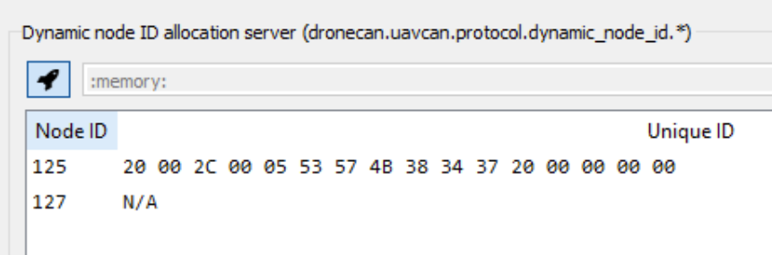
The DroneCAN GUI tool provides an easy-to-use node ID server. Simply click the rocket icon in the bottom right hand side to start the server:
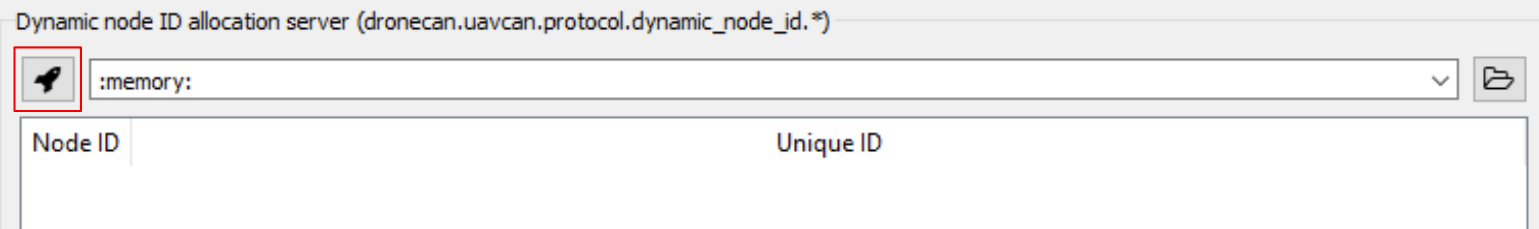
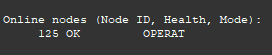
Once your module is powered on and connected to the GUI tool, your module will automatically begin requesting a node ID from the server, and the two will complete the handshake necessary to obtain a dynamically allocated node ID.
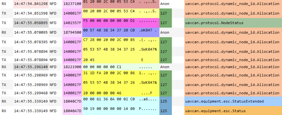
As seen through the CAN bus monitor tool, we see our node is allocated the ID 125, and immediately starts reporting its node status and ESC telemetry:
You will see the node ID and its associated UID in the DNA server window:
Receiving a Dynamically Allocated Node ID with PX4 and ArduPilot
PX4
The following is performed on PX4 version 1.15.1
Open QGroundControl, and connect your flight controller
Navigate to Vehicle Setup
Select Parameters, and scroll down until you find UAVCAN
In the UAVCAN settings, you will find
UAVCAN_ENABLE. Set this value toSensors and Actuators (ESCs) Automatic Config, save, and rebootNavigate to the MAVLink Console in Analyze Tools
Enter
uavcan statusIf you have not connected your module with your flight controller, you will not see any nodes listed
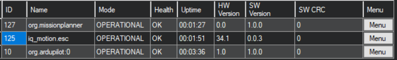
If you have already connected your module, you should see your node, and its allocated ID, listed as shown below
If you have not already, connect and power on your module
Once again, enter
uavcan status, and you should see your module has connected with the flight controller with a dynamically allocated ID
Now, if you reboot your module, and check
uavcan statusagain, you’ll find that PX4 allocates the same ID again
ArduPilot
The following is performed on ArduCopter version v4.5.7
Open Mission Planner, and connect your flight controller
Configure DroneCAN as described in DroneCAN Integration with an ArduPilot Flight Controller
If you have not already, connect and power on your module
Navigate to the DroneCAN configuration tool as described in Configuring your Module with DroneCAN Via ArduPilot
You should see your module with its allocated node ID as follows
Now, if you reboot your module, and check the DroneCAN configuration window again, you’ll find that ArduPilot allocates the same ID again
Calculating DroneCAN Bus Utilization
Background
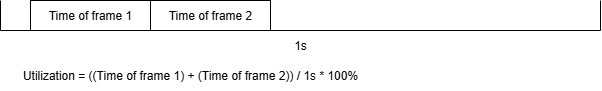
The basic premise of calculating DroneCAN bus utilization is to figure out how much time you spend sending DroneCAN messages compared to some period of time. For example, suppose your message takes 500ms to transmit. Then, in a 1 second period of time, that message takes up 50% of the available bandwidth.
The basic calculation we are going to perform is summarized in the image below:
DroneCAN frames are broken down as follows:

Please note that the Data bytes may be split further depending on whether or not the current frame is the beginning of a multi frame transfer. As specified by the DroneCAN specification, the data may be broken down as either:
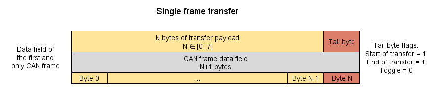
or
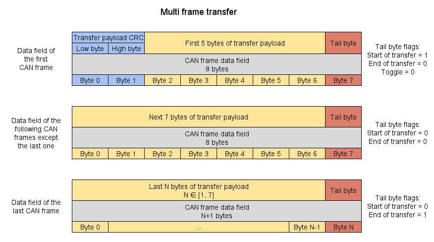
With no data (and thus no tail byte), this is 67 bits and 134us, and with a full 7 bytes of data (plus tail byte), this is 131 bits or 256us.
You can read more about the DroneCAN transport layer in the DroneCAN specification.
We can now easily apply this information to different types of DroneCAN messages. Shown here are the impacts of sending DroneCAN telemetry and RawCommands.
Utilization With DroneCAN Telemetry
By default, Vertiq modules transmit both the DroneCAN StatusExtended message as well as the EscStatus message.
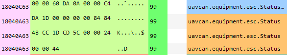
Each StatusExtended message sends exactly 56 bits of data, and only requires one full frame. This gives us about 131 bits of data.
Each EscStatus message transmits 110 bits of data, and requires 3 frames to transmit. The first two frames send a full 7 bytes of data (plus the tail byte, and including the 2 CRC bytes in the first frame as discussed above), and the final frame sends only 3 bytes (including the tail byte). This means the first two frames are about 131 bits, and the final frame will have 91 bits.
An example of a Vertiq module transmitting telemetry as viewed through the DroneCAN GUI tool is given below.
In total, Vertiq module’s DroneCAN telemetry requires:
131 bits StatusExtended + 353 bits EscStatus = 484 bits
So, we can find our utilization by:
484 bit/telem * 1/500Kbps = 968us to transmit telemetry at 500kbit per module. Assuming our time period of 1s, we find:
Transmission Frequency (Hz) |
Per Module Utilization of 1s @ 125Kbit (%) |
Per Module Utilization of 1s @ 250Kbit (%) |
Per Module Utilization of 1s @ 500Kbit (%) |
Per Module Utilization of 1s @ 1Mbit (%) |
|---|---|---|---|---|
1 |
0.3872 |
0.1936 |
0.0968 |
0.0484 |
10 |
3.872 |
1.936 |
0.968 |
0.484 |
50 |
19.36 |
9.68 |
4.84 |
2.42 |
100 |
38.72 |
19.36 |
9.68 |
4.84 |
250 |
96.8 |
48.4 |
24.2 |
12.1 |
500 |
193.6 |
96.8 |
48.4 |
24.2 |
In general, the percentage of total bus utilization over one second for telemetry only can be best estimated by:
Utilization (%) = (484 bit/telemetry) * (Transmission Frequency (Hz)) * 1/Bitrate * (Number of Module) * 100%
Utilization With DroneCAN RawCommands
The DroneCAN RawCommand message transmits one 14 bit command per each independent ESC commanded. So, the number of frames necessary to transmit a full RawCommand varies on the number of commands being transmitted per message. Some practical examples, and general formulae are provided below.
Let’s suppose that we need to control a generic quadcopter requiring only 4 independent commands. In this case, we only require 1 frame to send all of the required controls, and will fill the data portion of the frame entirely. We can visualize this in the DroneCAN GUI tool as illustrated below:

The result is a 131 bit frame. The utilization of a one second period is summarized in the table below:
Command Frequency (Hz) |
Utilization of 1s @ 125Kbit (%) |
Utilization of 1s @ 250Kbit (%) |
Utilization of 1s @ 500Kbit (%) |
Utilization of 1s @ 1Mbit (%) |
|---|---|---|---|---|
1 |
0.1048 |
0.0524 |
0.0262 |
0.0131 |
10 |
1.048 |
0.524 |
0.262 |
0.131 |
50 |
5.24 |
2.62 |
1.31 |
0.655 |
100 |
10.48 |
5.24 |
2.62 |
1.31 |
400 |
41.92 |
20.96 |
10.48 |
5.24 |
600 |
62.88 |
31.44 |
15.72 |
7.86 |
When using 4 or fewer ESC commands, we require only one frame to send all commands, and the utilization can be best estimated by:
RawCommand Utilization (%) = (131 bit/command - ((4 - Number of Commands) * (14 bits/command))) * (Command Frequency (Hz)) * 1/Bitrate * 100%
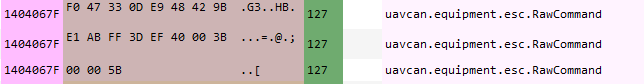
Once you extend beyond one frame, however, the calculation changes as the first frame of a multi-frame transfer requires a 2 byte CRC. So, suppose you are controlling 8 independent modules. Each individual command requires 14 bits, or 1.75 bytes. To transmit 8, we’ll require 14 bytes. With the 2 byte CRC, we need to send a total of 16 data bytes (ignoring tail bytes). Now, we need to figure out how many full, 7 data byte, frames we will have in sending 16 bytes. We find this by:
floor(16 bytes * (1 frame / 7 bytes)) = 2 full frames
Then, we need to find how much data remains which we can find by taking:
16 bytes - (2 full frames * 7 bytes/frame) = 2 data bytes remaining.
For this last frame, we need to account for the tail byte since we’re not sending a full frame, so we’ll have 3 total bytes of data in this final frame. Finding the total number of bits is then done by:
(131 bit/full frame * 2 full frame) + (67 bit/empty frame + (3 data bytes * 8 bit/byte)) = 353 bits
This example is visualized in the DroneCAN GUI Tool’s bus monitor here:
Now, we can once again find our utilization of 1 second at 500kbit by:
353 bit * 1/500Kbps * 100% = 0.071% Utilization
We can generalize utilization of RawCommands of more than 4 unique ESCs as the following steps:
Bytes for All Commands (C) = 1.75 bytes/command * (Number of Commands) + 2 bytes CRC
Number of full frames (F) = floor(C / 7)
Total bytes in last frame (L) = C - 7F + 1
Total bits (b) = 131 bitfull frame * F + (67 bit/empty frame + 8L)
Utilization of 1 Second (%) = b * 1/bitrate * Command Frequency (Hz) * 100%
For 6 commands:
Command Frequency (Hz) |
Utilization of 1s @ 125Kbit (%) |
Utilization of 1s @ 250Kbit (%) |
Utilization of 1s @ 500Kbit (%) |
Utilization of 1s @ 1Mbit (%) |
|---|---|---|---|---|
1 |
0.2 |
0.1 |
0.05 |
0.025 |
10 |
2 |
1 |
0.5 |
0.25 |
50 |
10 |
5 |
2.5 |
1.25 |
100 |
20 |
10 |
5 |
2.5 |
300 |
60 |
30 |
15 |
7.5 |
600 |
120 |
60 |
30 |
15 |
For 8 commands:
Command Frequency (Hz) |
Utilization of 1s @ 125Kbit (%) |
Utilization of 1s @ 250Kbit (%) |
Utilization of 1s @ 500Kbit (%) |
Utilization of 1s @ 1Mbit (%) |
|---|---|---|---|---|
1 |
0.2824 |
0.1412 |
0.0706 |
0.0353 |
10 |
2.824 |
1.412 |
0.706 |
0.353 |
50 |
14.12 |
7.06 |
3.53 |
1.765 |
100 |
28.24 |
14.12 |
7.06 |
3.53 |
300 |
84.72 |
42.36 |
21.18 |
10.59 |
600 |
169.44 |
84.72 |
42.36 |
21.18 |
DroneCAN Utilization of a Quadcopter
Now that we know how to calculate the utilizations of various DroneCAN messages, it is easy to extend our understanding to an entire vehicle of DroneCAN nodes. In order to do so, we simply need to sum together the impacts of each message. Let’s suppose that our flight controller transmits RawCommand messages at 400Hz, and that each of our modules transmits telemetry at 10Hz.
Since we are controlling four modules, we’ll need four commands per RawCommand message, and we’ll need only one frame to send them. Using our calculation above, we find that the utilization of these commands are:
Command Frequency (Hz) |
Utilization of 1s @ 125Kbit (%) |
Utilization of 1s @ 250Kbit (%) |
Utilization of 1s @ 500Kbit (%) |
Utilization of 1s @ 1Mbit (%) |
|---|---|---|---|---|
400 |
41.92 |
20.96 |
10.48 |
5.24 |
Then, we can use our telemetry calculation in order to find the impact of the four modules reporting telemetry as:
Transmission Frequency (Hz) |
4 Module Utilization of 1s @ 125Kbit (%) |
4 Module Utilization of 1s @ 250Kbit (%) |
4 Module Utilization of 1s @ 500Kbit (%) |
4 Module Utilization of 1s @ 1Mbit (%) |
|---|---|---|---|---|
10 |
15.488 |
7.744 |
3.872 |
1.936 |
After summing, we find the total utilization as:
Total Utilization of 1s @ 125Kbit (%) |
Total Utilization of 1s @ 250Kbit (%) |
Total Utilization of 1s @ 500Kbit (%) |
Total Utilization of 1s @ 1Mbit (%) |
|---|---|---|---|
57.408 |
28.704 |
14.352 |
7.176 |